
by Clive M. Law
The army cadet system has been long-established in Canada and cadet corps were authorized as early as 1861. Many of these units legitimately claim an earlier heritage having been formed as Rifle Associations. The majority of these cadet corps was linked to local schools and military instruction, including drill, marksmanship and First Aid, was provided by local Militia. Oversight of the instruction was often the responsibility of the schools and school teachers. In recognition of this the Department of Militia and Defence (M&D) authorized, in 1908, the Corps of School Cadet Instructors (CSCI)
Shortly after the establishment of the Corps, M&D published a description of the uniform to be worn by its officers. This was published as General Order 62 of 1909. The uniform was to consist of a double-breasted jacket ‘of ordinary civilian length’, fastened in front by two rows of four buttons, of Canadian Militia pattern. The sleeves to be plain with two small buttons placed on the seam. Finally, the jacket was to include cloth shoulder straps of blue cloth with gilt rank badges. The trousers were to be of the same colour and cloth and no stripes were authorized. CSCI officers were to wear the blue Field Service cap, of Infantry pattern. The cost of providing the uniform was to be borne by the officer and was not provided at public expense. Shortly thereafter, in August 1910, the infantry pattern forage cap was permitted as a replacement for the Field Service cap.
The description of the uniform caused considerable confusion in both the CSCI and tailor’s communities as it did not conform in any manner with the Militia uniform of the day. Clarification was requested and M&D replied that the ‘uniform’ was in fact a simple ‘civilian, double-breasted reefer jacket’ which would include two side pockets and a single breast pocket. Buttons were not to be worn on the pockets. The use of shoulder straps with rank badges would certainly have given this civilian attire an unusual appearance. The Quartermaster-General provided this justification for the dress; “This pattern was selected as it is simple and inexpensive, distinctive, and suitable for wear in school or on parade, and is intended for drill order only, as full dress uniform is not required.”
Militia & Defence drawing of the “King’s Cadet” badge.

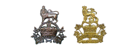
An example of the “King’s Cadet” badge, shown here in gilt. Image courtesy Peter Brydon.
Missing from the uniform was a distinctive cap badge to be worn on the Field Service or forage cap. This was finally addressed in August 1911, when the ‘King’s Badge’ was authorized for wear by Cadets. It appears that the Canadian High Commissioner to London was partly responsible for this. This person was none other than Lord Strathcona, whose interest in, and financial support of, the cadet movement in Canada was considerable. The Strathcona medal continues to be awarded to cadets to this day.
This ‘King’s Badge’ was the Royal Crest, i.e., a Crown surmounted by a lion rampant, below which was a simple scroll with the word ‘Cadets’. The Adjutant-General suggested in a letter that the King had approved the badge for use by cadets throughout the Empire. When shown to the Minister of Militia, Colonel Sam Hughes, he suggested that the badge include maple leaves in the design. These were sketched in, as well as an expanded scroll that now read “Cadets – Canada”, and the badge returned for the Minister’s approval. This unequivocally sets the date for this badge as early 1913 and that its use was for cadets and not instructors. Shortly after approval of the cap badge the Minister approved the use of a “Collar, Maple Leaf” (termed today as a General Service badge) and a ‘Canada’ shoulder title.
The first drawing of the “Canadianization” of the British badge.
A request for pricing was distributed and J.R. Gaunt was selected as the manufacturer. Unlike most badges produced on behalf of M&D, these were to be made available upon repayment (at 5 cents per badge). This approach was taken as it was felt that the ‘boys’ would keep or sell their badges rather than return them into Stores. This would result in additional work for M&D and the argument was made that the cadets would be pleased to pay the nickel. A rush order, for 1,000 badges, was placed so that delivery could be made prior to a cadet visit to England, scheduled for April of that year. Ultimately, a contract for 20,000 badges was issued.
While the design of the cadet badge was under discussion, a suggestion for a variation of the badge, to be worn by CSCI officers was proposed. This badge, in two styles, differed in that the scroll included the word “Instructor”. However, the badge was not approved and CSCI officers were left to wear the approved cadet badge.
Proposals for a specific badge for CSCI Officers. M&D did not approve either design.
While this variant was not accepted by M&D headquarters, the CSCI officers in British Columbia adopted a badge of their own. This badge featured ornate scroll-work of the initials, within a wreath and surmounted by a Crown. This badge was approved in July 1914, (although the outbreak of war may have caused the paperwork to disappear), and continued in wear until the disbandment of the CSCI in 1921 – the result of a re-organization of M&D.

The badge designed by CSCI officers in British Columbia and approved in July 1914.
With the authorization, in 1924, of a new cadet organization, the Cadet Services of Canada, the District Cadet Officer for Military District 11 (British Columbia) asked HQ if the CSCI badge could be modified to read ‘CSC’ (Cadet Services of Canada) over ‘NP’ (Non Permanent) and used by the recently approved organization.
Enquiries were made of J.R. Gaunt, which held the dies, and they replied that a change could be made. According to Gaunt, the earlier CSCI badge was “richly gilt, and burnished’. The modified badge was not approved and General Order 57 of 1925 re-affirmed that the authorized cap badge for CSofC officers was the badge authorized for cadets, i.e., the “King’s Cadet” badge with ‘Cadets – Canada’ in the scroll-work. The collar badges remained the Maple Leaf badge. Badges were to be bronze for wear on the khaki uniform and gilt for blue and scarlet uniforms. This GO also authorized the wear of the Infantry pattern uniform for CSofC officers.
In 1943, GO 28 authorized a separate badge for cadets, leaving CSofC officers the sole group to wear the “King’s Cadet” badge. This badge remained unchanged until June, 1953, when the Director of Administration DOA), Department of National Defence (DND) suggested to the Director of Militia and Cadets (DMC) that GO57/1925 was obsolete. DOA proposed that a new badge, featuring the entire title of the Corps (Cadet Services of Canada, and that the Tudor Crown be replaced with the St. Edward’s Crown in accordance with Canadian Army Order 64-5. Further, as collar badges were usually a miniature of the cap badge, that the Maple Leaf collars be replaced. Finally, it was recommended that cap and collar badges be gilt while the shoulder titles be brass.
The approved M&D drawing of the Canadian ‘King’s Cadet” badge. It was Sam Hughes who insisted on the addition of the maple leaves.
It would be March, 1955, before DMC replied, agreeing with the changes to the cap badge but suggesting that the collar badges be modified as; reduced by one-third in size (from 1-1/8-inch high and 1-inch wide, to 3/4-inch high and 13/16-inch wide), and that the shape of the Maple Leaf be changed to comply with the style approved by CAO 64-2. All other recommendations made by DOA were accepted. On 16 April, 1956, the drawings of the badges were approved.

The 1956 badge showing the ST. Edwards Crown and the modern (in 1956) Maple Leaf collar badges.
These would remain the authorized badges for the Cadet Services of Canada until the creation of the Cadet Instructor List, later re-organized as the Cadet Instructor Cadre, and the introduction of new badges.
Comparison of the badge initially approved for cadets and CSCI Officers, and the badge authorized for CS of C Officers
Ref – LAC, RG24, Volumes 29712 and 29713
You can ‘rate’ this article by clicking on the stars below.
by Clive M. Law
In early April 1951, the Commanding Officer of the 1st Battalion of the Royal 22e Regiment wrote to Army Headquarters to point out a discrepancy between the General Orders and the metal regimental title currently on issue. In his letter, Lt-Col L.F. Trudeau wrote that General Order 203 of 1941 states that the title should read ‘R22eR’ and that ‘the Ordnance issue badges for the R22eR do not bear the ‘E’ required by General Orders.’ Lt-Col Trudeau suggested, rather than change the titles, that the GO be amended.
This unexpected missive caught AHQ by surprise and an examination of both the GO and an actual example of the title in question was ordered. However, AHQ did not hold an example and one was requested from the Regiment. On 9 July, AHQ replied that the title was in accordance with Orders and that the measurements of ¼ inch for the ‘E’ and ½ inch for all other letters, and a width of 1 ¾ inches, were all in accordance with the General Order. The letter closed with the comment ‘In view of the above, the comments of the Commanding Officer, 1st Bn Royal 22e Regiment are not understood.’

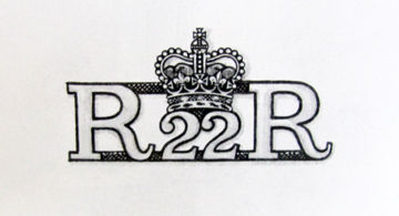
The title worn by ORs of the Royal 22nd Regiment. The CO of the 1st Battalion believed that the ‘E’ should be represented in a lower case ‘e’.
Shortly thereafter, the General Officer Commanding Quebec District weighed in by pointing out that the original order suggested that the (uppercase) ‘E’ should actually be a (lowercase) ‘e’. However, nothing came from this and both sides agreed to disagree.
It would be another five years before the question of metal shoulder titles for the R22eR was raised and, when it was, it again originated with the Regiment. In September 1956, Maj-Gen J.P.E. Bernatchez, General Officer Commanding (GoC) Quebec Command and a former CO of the Regiment, wrote on behalf of the Regimental Senate[1]
Bernatchez, in his role as GoC, wrote to support the Senate’s recommendation that metal and cloth shoulder titles include the Battalion numeral. HQ did not immediately deny the suggestion but instead asked the Regiment to report on their stock of existing titles, an estimated cost to produce new titles if approved, and the length of time it would take to acquire these. At the same time it was pointed out that this would increase the number of titles from one to six.[2] This seeming willingness was surprising as wartime policy was to avoid using battalion numbers on insignia[3]
Within two months approval was given for numerals to be added to the titles and the CO of the R22eR Regimental Depot was asked to review two proposals and to sign and return the design favoured by the Regiment. These two designs differed in having the numeral precede the Regimental abbreviation, or be placed above it. The chosen design was the latter and the dimensions were described as ‘letters ¼ inch high with the exception of the ‘E’ which is 1/8 inch in height.’ The width was to be one inch.

One of two designs submitted to the R22eR. This one featured the battalion numeral preceding the title.

Examples of the accepted design. None has been found for the 4th or 6th Battalions although they were most likely produced.
In approving the drawing the CO of the Regimental Depot identified that the title was to be made of brass for Other Ranks but ignored specifying the material for titles worn by officers and Warrant Officers First Class and stated in an accompanying letter that the new design would not be worn by officers or WO 1.
In response to a follow-up letter from AHQ, Maj-Gen Bernatchez informed them that the officers of the Regiment had worn a specific metal title since 1920 and ‘it would seem advisable that its use be continued.’ A sample of the title in question was included. Nonetheless, Bernatchez admitted that review of correspondence failed to uncover any information on how the badge came into use but it was requested Orders and Instructions for Dress be amended in order to authorize its continued use. The badge in question featured a crown above the R22eR.

The problematic title. This pattern was taken into wear in 1920-21 but with no authority for its use.
Once seen by AHQ, the R22eR title for officers caused concern. The use of the Crown on any insignia requires the approval of the Monarch and there was no evidence that such permission had ever been sought in the over 35 years that this title was in wear. When asked to explain its history the Regiment was at a loss. No records existed and it was evident that the badge had been brought into use without any approvals – at any level.

A comparison of the sizes of the two titles. As officers wear rank stars it was not possible to make the title much larger.
In an effort to further uncover the history of the title Bernatchez communicated with a number of retired officers as well as with the curator of the regimental museum. None could remember a formal request and all believed that the title dated from the era when the Regiment’s named was changed from 22 Infantry Regiment to Royal 22 Regiment.[4]
Further complicating the issue was a request from the Regiment to retain Tudor Crown (informally termed the King’s Crown) in lieu of adopting the St. Edward’s Crown as was dictated by Army Order 64-5 of 22 April 1953. The Regiment argued that the King’s Crown was taken into wear shortly after they had been awarded the title ‘Royal’ by H.M. King George V, in 1921. They included in their submission that the Regiment was formed under that King’s reign and was the first French-Canadian regiment to be made part of the Permanent Force. Under H.M. King George VI it was the only regiment to stand guard at Buckingham Palace formed completely of soldiers of non-British extraction (in 1938) and saw the Regiment grow from one battalion to three during his reign. Based on these points the Regiment sought permission to retain the Tudor Crown. Existing documents do not include AHQ’s answer to this request but it is known that the Crown did indeed change to the St. Edward’s Crown.
In November 1957, the Royal 22e Regiment made a formal request for retention of the historic metal shoulder title stating;
‘This Regiment is very proud of the fact that it is the first French-speaking Regular unit formed in the British Commonwealth and is most desirous of displaying its loyalty to the Crown by the addition of the Crown in the officer’s metal shoulder badge.’
Accordingly, the Governor General corresponded with Buckingham Palace and, on 17 December 1957, Government House confirmed that Her Majesty The Queen had given her approval. The badge is still worn today by officers and Chief Warrant Officers of the ‘Van Doos’.
This drawing, from the Royal Warrant, shows the badge worn since 1958 and still in wear today.
[1] A Regimental Senate is usually comprised of the serving Battalion/Regimental commanders as well as previous COs and the Honourary Colonel. They act as a Board of Directors for the Regiment.
[2] At the time the R22eR consisted of five battalions, numbered 1 to 4 and 6 as well as a plain title for members posted to the Regimental Depot and those assigned to extra-regimental duties.
[3] Some exceptions existed, most notably that of the First Canadian Parachute Battalion.
[4] Correspondence from 1926 show that there was a concern about the actual translation of the Regimental name. General Order 149 of 1922 gave the French translation of Royal 22 Regiment as ‘22e Regiment Royal’ which, when translated back into English would read as ‘22nd Royal Regiment’. Records indicate that the translation was supplied by the King’s Printer and they were duly informed. Of interest is that the titles clearly stated R22eR and a note on the file shows that no title was approved for wear by officers. This would indicate that the ‘crowned’ title was in wear as early as 1926.
You can ‘rate’ this article by clicking on the stars below.
by Bill Alexander
At the end of the Second World War, as in previous wars, the victors reaped the spoils of war. But, unlike previous wars the booty was not just gold, silver and fine art. Modern spoils were found in the technical and scientific wealth of the defeated German state. As death throes wracked the Nazi regime in the spring of 1945, the end of hostilities in Europe accelerated the pillage of the industrial German state. The Americans, British and Soviet Union had already begun to identify and locate material for exploitation. Canada as a major participant in the Allied war effort, scrambled to get a piece of the action before it disappeared behind the veils of state and industrial security.

Dr. Paul Larose, National Research Council, at the I.B. Farben plant in Germany, September 1945. DND photo.
In the summer of 1944, Canada had agreed to participate in the Combined Intelligence Objectives Sub-Committee (CIOS), an Anglo-American military and civilian group. Organized by the Supreme Headquarters Allied Expeditionary Forces (SHAEF), CIOS was tasked to:
…ferret out German industrial plant and research establishments in the wake of fast-advancing Allied armies after the June 1944 D-Day landings. (Koerner)
As the western Allies closed in on Germany during the last months of the war, the search intensified for advanced enemy science and technology. The CIOS investigations were joined by Consolidated Advance Field Teams (CAFT) and ‘T’ (Target) Forces, special British, Canadian, and American military units that followed behind front-line combat troops and located German industrial operations. These were secured for a later, more detailed examination. Despite a Canadian presence in these initiatives, lukewarm interest limited the extent of participation. [1]
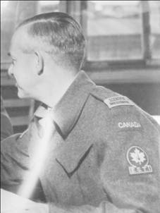
Unidentified member of the ESTI team, September 1945. DND photo.
After the German capitulation, the search intensified. The Field Information Agency Technical (FIAT), was established under SHAEF to “co-ordinate, integrate, and direct the activities of the various missions and agencies interested in examining, appraising, and exploiting all information pertaining to the German economy”. This was especially pressing for the Americans who had temporarily occupied key industrial areas in the soon to be Russian zones of occupation. The interests of Canada were obviously not a priority of SHAEF, nor the government of Canada. Canadian participation continued to be of limited scope and without direct instruction or control from the Canadian government. (Koerner) (SHAEF)
The lack of initiative on the part of the Canadian government to develop a policy and implement a program to identify and obtain scientific and industrial technology for Canada left a deepening feeling of anxiety and frustration in some official circles. Vincent Massey, Canadian High Commissioner in the United Kingdom, warned:
Whether we like it or not, a free-for-all is going on; and we must frankly face the alternatives either of joining in the scramble or of being left empty-handed. (Koerner)
The government finally responded in the spring of 1945 by organizing two committees to identify and implement a Canadian program. The first was the Canadian Advisory Targets Committee (CATC), essentially a military organization, formed in March 1945 and focused on military side of scientific and technological information. The second was the Joint Committee on Enemy Science and Technology (JCEST), composed of civilian scientists and military officers. Based in Ottawa it was established in July 1945. The purpose of CJEST was to identify and acquire German technology and scientific data, “including patents, plans, drawings and inventions having possible civilian use.” CATC and JCEST coordinated Canadian activities with CIOS and other related allied organizations. (Secretary of State for External Affairs)
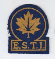
ESTI arm badge yellow flocked on blue felt. Author’s collection.
Together, CATC and JCEST:
…identified targets to be examined in Germany and elsewhere in Europe, drew up detailed lists of specific equipment or factories and plants required by the government or private businesses, and oversaw the work of Canada’s teams of scientific and industrial investigators. (Koerner)
Under this mandate, research teams were despatched to Europe. The first contingent of nine scientists embarked before VE Day and focused their investigations on science and technology of potential military use in the war against Japan. In the summer of 1945, Brigadier F.F. Fulton organized the main contingent of the JCEST team of 45 select Scientific Investigators. By late summer, they were overseas, focusing on civilian research.
The Scientific Investigators continued their work into the fall, with their mission accomplishments being highlighted by a press conference held at the Chateau Laurier in December, 1945. The record is unclear after that date, but it appears some Scientific Investigators continued research until the spring of 1946, when the repatriation of the Canadian army removed logistic support. Any remaining ESTI returned to Canada at that time. (Koerner)
ESTI Insignia
Due to the conditions in Germany and the nature of the work, the decision was made to send the team under the control of the army. The investigators were each issued two battledress uniforms and personal kit to facilitate their work. These stores, while military in nature, were to be charged to the Ministry of Munitions and Supply, while the army supplied logistical support for the contingent. To clearly identify the team, unique insignia were designed and issued. A general list metal CANADA cap badge was worn on the standard pattern khaki beret. Each scientist under the authority of the JCEST was issued four CANADA nationality titles plus a pair of SCIENTIFIC INVESTIGATOR shoulder epaulet slip-on badges and two arm patches, EST I. (Enemy Science and Technology Investigator). (E.B. Wilson) (Canadian Army Photo 57239/N) (Department of Reconstruction File 7-BF-1 (s)) (Canadian Army Photo 57239/N) (E.B. Wilson)
The CANADA nationality titles were the standard worsted pattern issued to all Canadian army personnel, buff coloured embroidery on khaki worsted wool backing. The SCIENTIFIC INVESTIGATOR shoulder badges were made as a slip-on, black printed on a heavy tan coloured cotton drill material. Records indicate 128 pairs were initially obtained from the Travers Apron Ltd of Ottawa, with an additional 100 pairs in a second order in September of 1945. (R.McColm)

SCIENTIFIC INVESTIGATOR slip-on, printed on heavy cotton drill. Author’s collection.
The shoulder patch used the abbreviation EST I, for Enemy Science and Technology Investigator. Made using the flocked technique, it consisted of a maple leaf sprayed in yellow on a circular blue felt base. The leaf was enclosed in a near full circle with a tablet at the bottom of the circle bearing yellow lettering E. S. T. I. At least two hundred of these titles were obtained from Unique Products Co. Toronto. (R.McColm) These insignia identified the members of CJEST as they performed their investigations over the summer and fall of 1945.
References
Burgess F.A. Lt.-Col. for Brig. F.F.Fulton, Canadian Advisroy Targets Committee. “CIOS INVESTIGATORS: UNIFORMS and EQUIPMENT.” Letter. March 28, 1945. LAC RG24 Vol 10040.
Canadian Army Photo. “Photo 57239/N.” 1945.
Department of Reconstruction File 7-BF-1 (s). “Backgrounder EST I Press Conference.” LAC RG 25 Volume 5713 File 7-BF-1 (s), 14 December 1945.
E.B. Wilson, Brigadier. “Clothing and Equipment for Cdn Scientists Memo.” Ottawa: LAC RG 24 Vol 10049 File 13 / Cloth /4 /13, 14 August 1945.
Koerner, Steven J. “Technology Transfer from Germany to Canada After 1945.” Comparative Technology Transfer and Society (Volume 2, Number 1, April 2004. ): pp 99-124.
R.McColm, Colonel. “Badges Shoulder Printed Scientific Investigator Badges Emb. Colored EST I Letter.” Ottawa: LAC Badges Cdn Active Service Force RG 24 Series A Vol 2184 File Hq 54-27-60-3 Vol. 7, 25 September 1945.
Secretary of State for External Affairs. “Telegram No 1632.” LAC RG 25 Volume 5713 File 7-BF-1 (5), 16 July 1945.
SHAEF, Advance Headquarters. “Establishment of Field Information Agency Technical (FIAT) of G-2 Supreme Headquarters AEF.” LAC RG 25 Volume 5713 File 7-BF-1 (5), 31 May 1945.
You can ‘rate’ this article by clicking on the stars, below. You can also leave comments at the bottom of this page.
by Roger V. Lucy
Canada raised an Airborne battalion in WWII, which served with the British 6th Airborne Division. For combat these soldiers were issued with the British Helmet, Steel, Airborne Troops, Mk.I (which had a four-point leather harness) and, after 1944, the Helmet, Steel, Airborne Troops Mk.II, with a three point web suspension. For training purposes in the UK, the canvas and sorbo rubber Airborne Troops Training Helmet, Standard Pattern was also issued. Those training in the USA and Canada initially used the US Riddle training helmet or the steel M1 Parachutist Helmet. Later British airborne steel helmets, which were judged to be superior, being less liable to fall off or to foul the parachute shrouds, were procured for training in Canada.

Preparing for their Normandy descent, these soldiers wear Helmets, Steel, Airborne Troops Mk.I heavily covered with netting and scrim.
Immediately after the War Canada’s airborne forces were reduced to a single company, drawn from the Princess Patricia’s-Canadian Light Infantry (PPCLI). By the end of the decade, however, Canadian defence policy had changed to meet the possible threat posed to Canada’s vast arctic territory by a potential Soviet aerial descent. To counter this perceived threat, a much expanded airborne capacity was created, the rapid reaction Mobile Strike Force (MSF). The MSF was envisaged as a force able to operate anywhere in Canada, including the Arctic, and required the expansion of Canada’s airborne cadre from company to battalion and then to nominally brigade strength. This put great stress on the supply of a variety of airborne equipment from transport aircraft to helmets. In 1951-2 the MSF required 3,000 paratroop helmets. The receipt of 900 helmets from the UK in 1948, had provided sufficient helmets to equip the newly expanded PPCLI battalion, but not the other battalions, nor the Joint Airborne Training Centre (JATC) at Rivers, Manitoba. When 400 additional helmets were ordered from the British War Office in June 1951, DND was informed that airborne helmet production had ceased at the end of the War and the British had no plans for procuring new helmets for its own use. The Canadian order was too small to justify reopening the line.
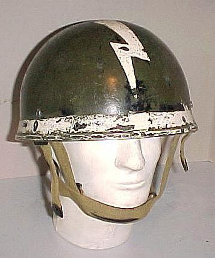
To meet this deficiency a number of Canadian Helmet, Crash, Motor Cyclists, Steel were converted to airborne use and issued to the Van Doos and RCR’s airborne battalions. The conversion consisted of inserting a top pad, cutting off the curtain and chin-strap and boring four holes in the rim to take a leather harness based on that of the Mk.I Airborne helmet. The helmets were worn reversed, so the brow pad on the DR helmet became a neck support on the Airborne helmet. Reports from the units indicated that these conversions were considered unsatisfactory.
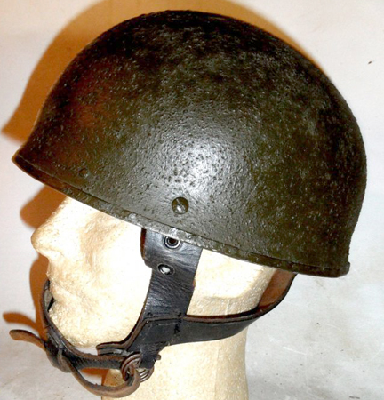
An example of a Canadian-made steel DR helmet converted to an airborne helmet. It has been painted Paint, Exterior, Flat Green No 3-213. Author’s collection
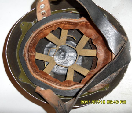
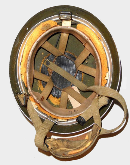
The interior of a converted DR helmet, the helmet has been reversed, so the brow pad of the DR helmet now supports the back of the soldier’s head. Author’s collection
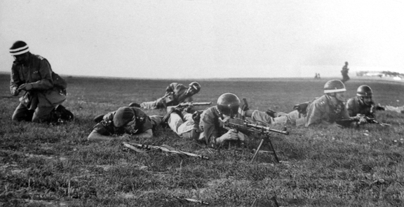
This photograph shows the RCR Company of the MSF exercising at Malton. They appear to be wearing converted DR helmets. Note the white bands which seem to indicate officers.
This converted DR helmet was later fitted with a new liner and a web Mk.II harness. Peeling away some subsequent coats of paint revealed markings similar to the soldiers exercising at Malton. Author’s collection
In 1952 the British UK resumed airborne helmet production and on 30 January 1953, DND ordered 4,000 new-production Helmets, Steel, Airborne Troops, Mk. II from the manufacturer Briggs Motor Bodies, These were delivered by the end of the year and are readily identified by having BMB MK2 C335-53 (the exact batch number varies somewhat) stamped on the brim and BMB 1953 and the size stamped on the sweat-band.

This 1953-dated British airborne helmet has received a coat of Paint, Exterior, Flat Green No 3-213.and has a Van Doos decal on the left side. Author’s collection
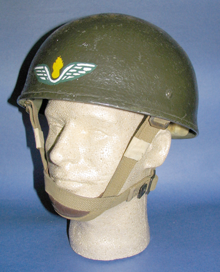
A similarly painted helmet but with airborne Royal Canadian Engineers insignia at the front. W.E. Storey collection

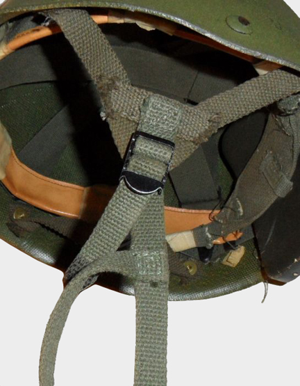
The interior of a the 1953 Helmet, Steel, Airborne Troops Mk.II, still in its original British paint.
In August 1960, the US M1 helmet became the standard helmet for the Regular Army. It was intended to supplant the British Airborne helmet, with the M1 Parachutist Helmet, fitted with the nylon Type II Combat Liner. However, while an example of the parachutists’ version of the US nylon liner was obtained for evaluation in 1962, and the purchase of 6,000 authorized in November 1963, they were slow to enter serial production. In the interim, the British airborne helmets designated “limited standard” and remained in service. There were still 2,131 British Airborne helmets in the Ordnance stocks at Shilo in June 1960, but by late 1963 the larger sizes were no longer available. It is probably at this time that numbers of old airborne Mk.I and converted DR helmets were converted to Mk.II standard, and numbers of the 1953 helmets were refurbished. These helmets have post war Airborne Mk.II harnesses, as well as substitute sweat bands backed by crumbly yellow foam-rubber padding. The size is marked in felt pen.
The interior of the much converted ex-DR helmet, shown above with its replacement liner. Note the very poor quality foam rubber. Author’s collection
The harness of the British airborne helmet was found to be incompatible with the new Canadian NBCW mask It was also unpopular with the troops carrying out training jumps, who complained that its weight tended to cause neck-strain, and that it gave no protection to the lower head and jaw from the parachute shrouds. Some soldiers took to using privately purchased football helmets for training. When, in August, 1964, CJATC sought formal permission for their use, General Allard, forbade their use altogether, noting they were also banned in the USA. In November, 1965, with no deliveries of nylon M-1 parachutists liners in sight, experiments were undertaken to see if a parachutist chin-strap could be fitted to the M-1 steel body. While it was determined that this was feasible, no steps seem to have been taken to issue these helmets in place of British airborne helmets.
Issues of the US-made parachutists helmets (Helmet Steel Parachutist, GS MK I) finally began in the late-1960s and the British airborne helmets were retired. Essentially the M1 parachutist helmet resembled the standard M1 helmet, except the liner was fitted with two web yokes to which were buckled a web chin-strap. On each side of the liner there was a press stud to which was snapped the end of a short extension of the steel pot’s chin-straps. Further tests were carried on M1 parachutists’ helmets at Rivers Manitoba in June1967. These concluded that the nylon Combat Liner Type II was generally satisfactory, except for the way in which its chin-strap was fastened. The brass wire claw buckles on the yokes were difficult to adjust easily and the brass eyelets had a tendency to tear away. Instead the eyelets were omitted and the buckles replaced by two slide buckles. The ends of the modified strap were heat-treated to prevent fraying. So modified, these helmets served on until 1997, when the kevlar CG634 helmet was adopted. This helmet is suitable for use by both airborne and ground troops,

The nylon Type II Combat liner worn under the M1’s steel pot

A Canadian issue M1 Parachutist helmet.
A close-up of the modified strap attachments on a Canadian-modified M1 Parachutist’s Helmet.
Markings and Insignia
Most British airborne helmets retained either their olive factory paint or were repainted in the universal dark green paint used on Canadian Army vehicles (and everything else of that period) termed: Paint, Exterior, Flat Green No 3-213. Liberal use of nets and scrim remained the norm for field service. At the same time however it became the practice to distinguish the helmets worn by different units, arms and services, either with decals, painted insignia or by painting them in branch colours. Infantry regiments often painted their helmets white; jump instructors red; Signals Corps blue and white; Ordnance Corps Red and Blue etc. Contemporary photographs show these coloured helmets used on exercises, perhaps as a way to identify different units and functions. This practice of applying unit insignia or colours to M1 parachutists’ helmet seems to have been rarely if ever practiced.

The RCE helmet, shown above, photographed being worn in service. W.E> Storey Collection
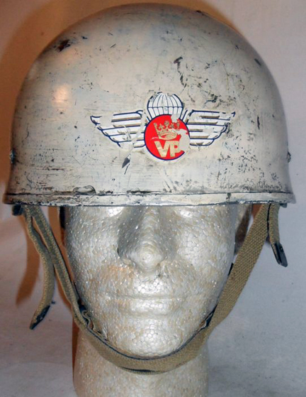
This white painted helmet with the PPCLI’s insignia began life as a Helmet Steel Airborne Troops Mk.I, but was later converted to a Mk.II. Author’s collection
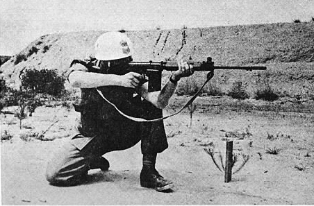
This photograph from a pamphlet an early manual on the FNC1 rifle shows a another white airborne helmet, with rank insignia. W.E. Storey Collection

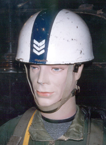
This picture, taken in 1956, shows jump instructor wearing red helmets, with rank insignia.

An example of a similar instructor’s helmet, held by the Canadian War Museum. The interior markings indicate it was a wartime issue Mk.II.

A maroon painted Mk.II Airborne helmet.Author’s collection
An airborne signaller’s helmet, displayed at the RCCS Museum in Kingston. Photo courtesy W.E. Story

An airborne helmet worn by a Lieutenant of the Royal Canadian Ordnance Corps. There is a similar helmet in the RCOC Museum. Author’s collection

Ready to jump, an airborne medic with his helmet painted in the colours of the RCAMC

This black-painted Mk.I Airborne helmet has the red and yellow flash of the Royal Canadian Armoured Corps. Jan Nowak collection.
You can ‘rate’ this article by clicking on the stars below. You can also leave a comment at the bottom of the page.
by Clive M. Law
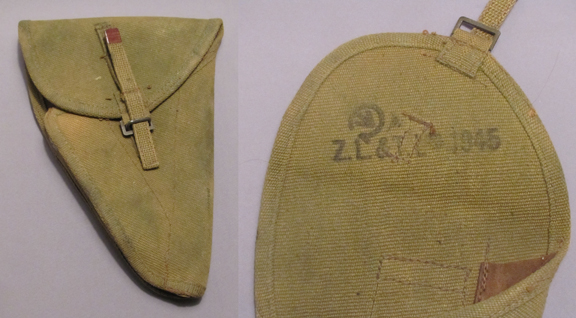
Shortly after the Japanese attack on Pearl Harbour, and its resulting status of an Axis nation, China approached Canada with the hopes of obtaining critically needed war materiel. This included field guns, trucks and Bren light machine guns. With Canada’s agreement to supply these, a Chinese delegation travelled to Canada. During their visit of the John Inglis plant at Toronto, they asked if Canada could also supply semi-automatic pistols, specifically the Model 1935 Grande Puissance manufactured by Fabrique Nationale, of Herstal, Belgium. Over a period of several months Inglis reverse-engineered the pistol and started manufacture of the pistol. The terms of the agreement included that the each pistol was to include a spare magazine as well as either a cloth holster or a wood combination holster and shoulder stock. Inglis sub-contracted the manufacture of the holsters to Zephyr Loom & Textile (ZL&T), an established, Toronto-based, manufacturer of Pattern 1937 Web Equipment for the Canadian Army.
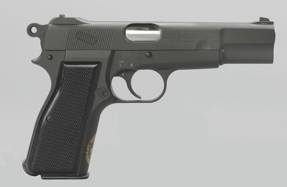
An example of an Inglis-made Browning Hi-Power, 9mm pistol as produced for the Canadian Army, ca. 1944. Author’s collection
After a first shipment of 4,000 pistols was made the contract was cancelled by the Canadian government due to the inability to deliver the pistols to the Chinese Army. The remaining stock was then accepted by both the Canadian and British Armies – this included the holsters. The holster, made of webbing material featured a single fold-over flap opened with a quick-release tab. This holster was officially termed “Holster, C, No. 2, Mk 1”. Almost immediately complaints were raised about the extremely tight fit of the pistol in the supplied holster. Inglis denied any responsibility, stating that the holster was constructed to Chinese specifications.
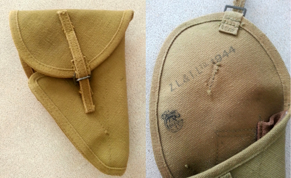
Standard issue first pattern (often termed ‘Chainese pattern’ in recognition of the original contract). Anthony Sewards collection
Faced with the situation the Canadian Department of Munitions and Supply set about redesigning the holster to better suit the Canadian Army’s needs. The result was a double fold-over design that offered ample protection to the pistol and provided for quick and easy withdrawal of the pistol. Both models made provision for a spare magazine. The quick-release tab was also improved. As with the early model, this model was also manufactured by ZL&T. This model was officially known as the “Holster, C, No. 2, Mk 2”.
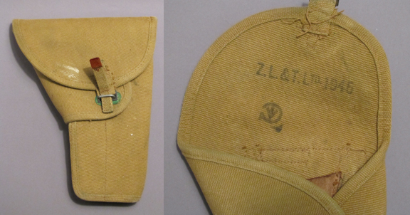
Standard issue second pattern holster. Clearly visible are the date and manufacturer’s stamps.
In addition to the obvious physical differences it is worth noting that the early models are all dated 1944 while the second model is dated 1945. In addition, some models will be found in the natural tan colour of unfinished web material while others may be found in a green finish, the result of dying the cotton prior to looming.
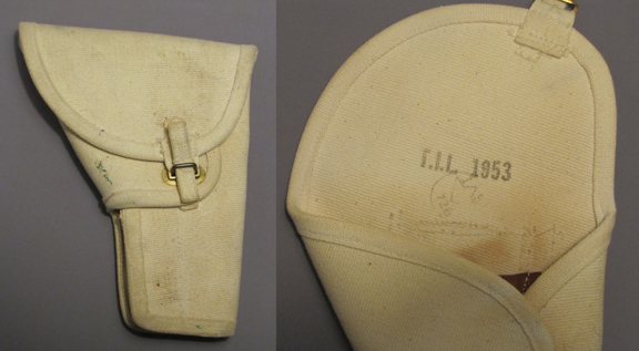
Second pattern holster, manufactured by Textile Industries Ltd., and dated 1953. TIL was a re-incarnation of the Second World War Zephyr Loom & Textile (ZL&T) the original producer of these holsters. Author’s collection
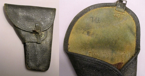
Second pattern holster with a black finish as used by Armoured and Rifle units postwar. This model also exhibits the ‘TPL’ stamp, denoting a tropical anti-fungal treatment. Author’s collection
However, there exist two rare models that bridged these two production models. One was a minor improvement by Canada which saw the early type quick-release tab replaced with the improved type – but still utilizing the early holster body. In addition to the quick release tab this holster can be identified by the use of a single rivet attaching the spare magazine sleeve to the holster body (in lieu of the two rivets used on the first pattern) and the 1945 date stamped on the inside of the flap.
Canadian modification to the first pattern holster. All such examples are dated 1945 and feature a modified quick-release tab. Author’s collection
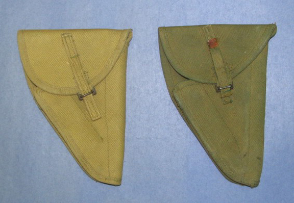
Two variants of the first pattern holster, left, the tan-coloured original featuring the original quick-release tab. Right, a green example showing the second pattern of release tab. Ed Storey collection
Little is known of the other experimental model, developed by the British, and it is possible that only a single example was produced. This style retains the general shape of the first pattern holster but features a deep cutout to allow the user to gain a better grip on the pistol and thereby facilitate its removal from the holster. The single known model was manufactured by the Mills Equipment Company, of London, England, and is dated 1944. No surviving examples are known and only a single photograph, located in DND files, testifies to its existence.
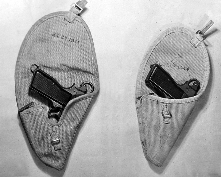
This photograph shows the only known (and possibly sole) example of the British proposed modification which featured a relief cut in the web material. MilArt photo archives
The second pattern holster remained in use through the Korean War until its ultimate replacement by a holster designed for use on the Canadian Pattern 1951 Web Equipment. Nonetheless, as the new webbing was not a universal issue for many years the second pattern holster can be found with manufacture dates into the 1950s. Examples can be found Blanco’ed white, for use by Canadian Provost Corps, as well as painted black for wear by members of the Royal Canadian Armoured Corps. The same style can also be found in black leather (with a number of variations of hangers) as well as in a white ‘parade’ version, made of lightweight plastic.
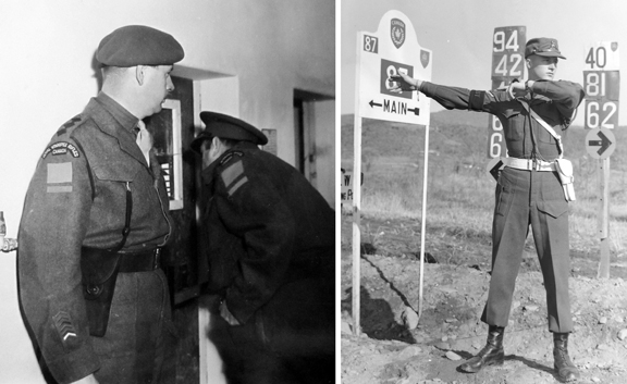
Left, An Officer of the Royal Winnipeg Rifles wearing a blackened second pattern holster in keeping with Rifles’ tradition, ca. 1945.
Right, an immaculately turned out ‘Provost’ directing traffic in South Korea, 1952.
In addition to variations in colour and manufacturer’s marks, some holsters (almost exclusively second pattern) can also be found with a ‘TPL’ marking under the flap, indicating that it has been treated with an anti-fungal process for Tropical use.
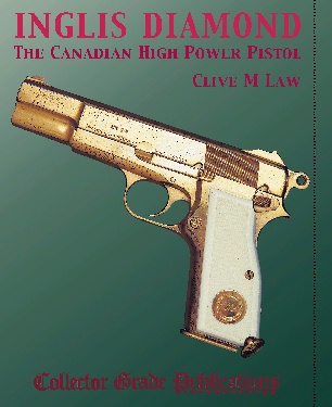
Additional information on the Canadian pistol and its many holster variations can be found in the author’s book “Inglis Diamond” available from Collector Grade Publications at http://www.collectorgrade.com/bookshelf1.html
Did you enjoy this article. You can ‘rate’ it by clicking on the stars below. You can also leave comments – see bottom of this page.
by Bill Alexander
Early in the Second World War, the importance of airpower was quickly and forcefully demonstrated. The German blitzkrieg and the lightning fast expansion of the Imperial Japanese Empire were based upon new applications of the role of aircraft in warfare. But, airpower, however impressive in tactical and strategic deployments, had a significant vulnerability. As the Germans had forcefully shown on Crete and in other campaigns, and the Japanese in the Far East, aircraft required landing strips. Defending aircraft and their air fields became a significant component of military planning and deployments.
Canada, with her vast size and immense distances, had early on embraced aircraft as a means of communication and transportation. With the need for home defence, and the implementation of the British Commonwealth Air Training Plan early in the Second World War, airpower became a central component in the Canadian war effort. It also became apparent, that though the majority of fighting was overseas, Canada was vulnerable. U-boats were active along the Atlantic coast and in the Gulf of St Lawrence. Threats, real or perceived, of German intrusions on Canadian territory troubled NDHQ. With Pearl Harbour, and Japanese aggression in the Pacific, threats to Canadian security were imminent on two coasts. The possibility of saboteurs, armed landing parties, armed incursions, or even a full scale invasion made attacks on Canadian airfields a real possibility. Denying airfields to the enemy and protecting them from incursions and sabotage became a military necessity. Canada’s home defence divisions were tasked with protecting these essential military assets. (C.P.Stacey 177)
Airfield defence required that several potential threats be addressed. Anti-aircraft defence and flight line security were the respective responsibility of the RCA and RCAF. For defence from enemy ground attack or incursions, active and reserve units of the Canadian army, including some Veterans’ Guard Companies were initially detailed to protect the perimeter of the airfields. (Tonner and Stacey)
Even with these steps, there was an appreciation that the airfields were still vulnerable to incursions or assaults by organized ground or airborne forces:
The rapid development of technique shown by the enemy in the seizure of airfields in the European and Asiatic theatres of war stressed the need for providing as a counter-measure a more specialized type of defence unit than the regular infantry battalion. In CANADA this requirement was first met by the mobilization, in May 1942, of twelve Aerodrome Defence Platoons, five of which were slated for employment in Pacific Command. Each platoon was raised on an establishment of 1 officer and 43 other ranks, and comprised a headquarters, two sections each mounting three 2-pdr A/Tk guns on carriers, and a section of two carriers with 3inch mortars. Two Ronson flame-throwers were added to establishment on reorganization of the platoons (into) Aerodrome Defence Companies in October.
The addition of the new platoons to existing forces at RCAF aerodromes or advanced air bases provided for a mobile defence force at each station, consisting of the aerodrome defence platoon, carrier platoons and lorry-borne infantry, whose special role was that of breaking up and destroying any enemy attack before it reached the inner perimeter, manned by RCAF personnel. (Report No.3 Para 76)
Defence of Canadian airfields became a specialized tasking, with dedicated units of the Active Army in Canada trained to respond to threats to the airfields. The organization of the airfield defence units evolved over the period of their existence. The Aerodrome Defence Platoons were the first manifestation of the force, but due to the inordinate amount of administrative work placed upon the platoon officer, the establishment was changed to company strength in November of 1942.
General Order No. 495/1942, Dated: 31st December, 1942, Effective Date: 23rd November, 1942.
G.O. 495/42 – CONVERSION AND REDESIGNATION – ACTIVE UNITS –
1. The Conversion and Redesignation of the under mentioned Active Units of The Canadian Army is hereby authorized:
Present Conversion and
Serial Designation Serial Redesignation Authorized
1301 1st Aerodrome Defence Platoon 1301 1st Aerodrome Defence Company
1302 2nd Aerodrome Defence Platoon 1302 2nd Aerodrome Defence Company
1303 3rd Aerodrome Defence Platoon 1302 3rd Aerodrome Defence Company
1304 4th Aerodrome Defence Platoon 1304 4th Aerodrome Defence Company
1305 5th Aerodrome Defence Platoon 1305 5th Aerodrome Defence Company
1306 6th Aerodrome Defence Platoon 1306 6th Aerodrome Defence Company
1307 7th Aerodrome Defence Platoon 1307 7th Aerodrome Defence Company
1308 8th Aerodrome Defence Platoon 1308 8th Aerodrome Defence Company
1309 9th Aerodrome Defence Platoon 1309 9th Aerodrome Defence Company
1310 10th Aerodrome Defence Platoon 1310 10th Aerodrome Defence Company
1311 11th Aerodrome Defence Platoon 1311 11th Aerodrome Defence Company
1312 12th Aerodrome Defence Platoon 1312 12th Aerodrome Defence Company
1313 13th Aerodrome Defence Platoon 1313 13th Aerodrome Defence Company
1314 14th Aerodrome Defence Platoon 1314 14th Aerodrome Defence Company
1315 15th Aerodrome Defence Platoon 1315 15th Aerodrome Defence Company
Even with this reorganization, the management and control of the air defence companies continued to be an administrative headache, and the companies were allocated to two Air Defence Battalions, effective 19th July, 1943. These new air field defence battalions were formed by converting two existing Canadian regiments, the 1st Battalion, Le Regiment de Chateauguay, to the 1st Airfield Defence Battalion (Le Regiment de Chateauguay (Mit.), C.I.C. and the 3rd Battalion, The Regina Rifle Regiment, C.I.C. to the 2nd Airfield Defence Battalion(The Regina Rifle Regiment), C.I.C. All existing Aerodrome Defence Companies were put under their command, with the 1st Airfield Defence Battalion under Atlantic Command, and the 2nd Airfield Defence Battalion under Pacific Command.
General Order No. 439/1943, Dated: 1st November, 1943, Effective Date: 19th July, 1943.
G.O. 439/43 – SERIAL NUMBERS – ALLOTMENT OF – The following Serial Numbers are hereby alloted to the various Sub-Units of Serial 1071 – 1st Airfield Defence Battalion (Le Regiment de (Le Regiment de Chateauguay (M.G.)), C.I.C. and Serial 1073 – 2nd Airfield Defence Battalion (The Regina Rifle Regiment), C.I.C., as indicated hereunder:
Serial Unit
1071A Battalion Headquarters, 1st Airfield Defence Battalion (Le Regiment de Chateauguay (M.G.), C.I.C.
1071B No. 1 Company, 1st Airfield Defence Battalion (Le Regiment de Chateauguay (M.G.)), C.I.C.
1071C No. 2 Company, 1st Airfield Defence Battalion (Le Regiment de Chateauguay (M.G.)), C.I.C.
1071D No. 3 Company, 1st Airfield Defence Battalion (Le Regiment de Chateauguay (M.G.)), C.I.C.
1071E No. 4 Company, 1st Airfield Defence Battalion (Le Regiment de Chateauguay (M.G.)), C.I.C.
1071F No. 5 Company, 1st Airfield Defence Battalion (Le Regiment de Chateauguay (M.G.)), C.I.C.
1071G No. 6 Company, 1st Airfield Defence Battalion (Le Regiment de Chateauguay (M.G.)), C.I.C.
1073A Battalion Headquarters, 2nd Airfield Defence Battalion (The Regina Rifle Regiment), C.I.C.
1073B No. 1 Company, 2nd Airfield Defence Battalion (The Regina Rifle Regiment), C.I.C.
1073C No. 2 Company, 2nd Airfield Defence Battalion (The Regina Rifle Regiment), C.I.C.
1073D No. 3 Company, 2nd Airfield Defence Battalion (The Regina Rifle Regiment), C.I.C.
1073E No. 4 Company, 2nd Airfield Defence Battalion (The Regina Rifle Regiment), C.I.C.
1073F No. 5 Company, 2nd Airfield Defence Battalion (The Regina Rifle Regiment), C.I.C.
1073G No. 6 Company, 2nd Airfield Defence Battalion (The Regina Rifle Regiment), C.I.C.
1073H No. 7 Company, 2nd Airfield Defence Battalion (The Regina Rifle Regiment), C.I.C.
1073J No. 8 Company, 2nd Airfield Defence Battalion (The Regina Rifle Regiment), C.I.C.
1073K No. 9 Company, 2nd Airfield Defence Battalion (The Regina Rifle Regiment), C.I.C.
This reorganization was short lived. The need for air field defence quickly diminished, and many companies were disbanded. The 1st Airfield Defence Battalion was re-converted and re-designated the Regiment de Chateauguay effective September 1, 1944, and then disbanded effective January 18, 1945. ( Le Regt de Chateauguay had been sent to the UK and was disbanded upon arrival there.) The 2nd Airfield Defence Battalion had been disbanded effective November 15, 1943.

An officer and Sgt of the Régiment de Chateauguay at Goose Bay air field. Circa 1944.
Aerodrome Defence Company Insignia.
No distinctive metal cap or collar badges were approved for the Air Field Defence Battalions or their predecessors. Initially, the intention was that the Aerodrome Defence Companies were to wear the Infantry Corps badges. These were not available until 1943, but there is no evidence that they were worn by the Aerodrome units.
In 1942, the Canadian Army had approved the wearing of coloured embroidered shoulder titles for units on active service in Canada. A unique shoulder title was made for the Aerodrome Defence Companies. The title reads AERODROME DEFENCE COMPANY on one arched up line, in red embroidered thread on “French blue grey” melton material. At least 5,000 Aerodrome titles were ordered in June, 1943. Additionally, there exist numerals, worn sub-nominally to identify the various companies. An example of the “4th”, denoting the 4th Company is illustrated below. There have been suggestions that sub-nominals were produced for all companies, but this has not been substantiated. To date, no authorization for the sub-nominal numerals has been located, and no comprehensive list has been compiled, but examples of the following are confirmed in collections: 4, 6, 7, 8, 9, 10, 11, 12, 13, 14, and 15. It is likely that examples were made for 1, 2, 3, and 5. (G.W.Cavey , Memo July 1, 1943.)
The Air Field Defence Battalions adopted the coloured embroidered titles of the parent regiments when they were reorganized in late 1943.

Aerodrome Defence Company title.
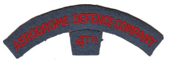
Shoulder title to the 4th Aerodrome Defence Company
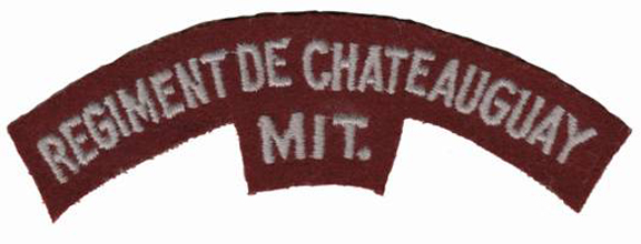
The Régiment de Chateauguay (Mitrailleuses) Second World War era embroidered shoulder title.
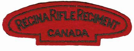
The Regina Rifle Regiment Second World War era shoulder title. The same pattern was worn by the 1st and 3rd Battalions.
Bibliography
C.P.Stacey. Six Years of War. Ottawa: Minister of National Defence, 1955.
Directorate of History. AHQ REPORT NO. 3, THE EMPLOYMENT OF INFANTRY IN THE PACIFIC COAST DEFENCES, Aug 39 – Dec 43. Ottawa: Department of National Defence, 1986.
G.W.Cavey, Colonel, D.O.S. (G.S.). “Memo Badges Embroidrered Coloured, to Dept of Munitions & Supply.” LAC RG 24, Volume 2186, File HQ S4-27-60-13 Volume 3., 1 July 1943.
Tonner, Mark. On Active Service. Ottawa, Ontario: Service Publications, 2006.
by Clive M. Law
The Governor General’s Foot Guards were established by General Order 16 of 7 June, 1872. The GO was very specific in that “The Corps to be special and under the direct command of the Adjutant-General”. This unusual chain of command immediately set the GGFG aside from other Militia regiments of the day and set the tone that the GGFG were the nation’s regiment and not a City or Rural regiment. In fact, one of the prime reasons for the establishment of a Guards Regiment at Ottawa was to provide the Governor General, and to an extent Parliament, with the ceremony due his office.
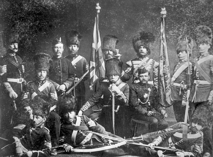
Officers, Warrant Officers and Sergeants of the Governor General’s Foot Guards, ca. 1873. Lt-Col Ross is shown seated, centre.
As a Regiment of Foot Guards the GGFG adopted the uniform of their Allied Regiment, the Coldstream Guards. As such they adopted the red plume for the bearskin cap and wore their buttons in pairs.[i] For the better part of the next century, the GGFG looked to Britain for guidance in all matters pertaining to Dress and their headdress and cap badges readily testify to this.

Officers of the Regiment, ca 1885. Note the three officers in cocked hats. These are the Medical Officer, Quartermaster and Paymaster who, as non-combatant officers, did not wear the bearskin cap.
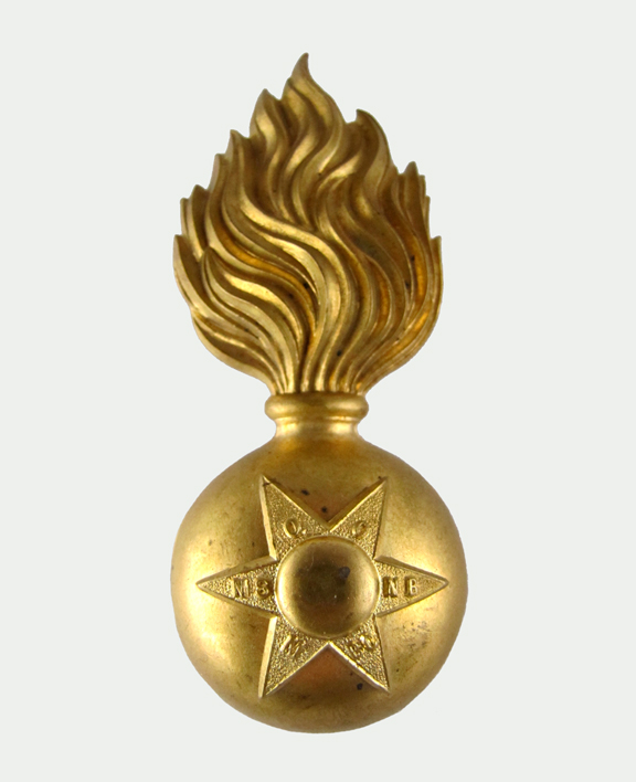
In addition to the bearskin cap, the GGFG wore the variety of headdress authorized by Dress Regulations of the time. In the late 1800s these included the Field Service Cap (Torin pattern), the Forage cap and, for ‘non-combatant’ officers, a cocked hat in lieu of a bearskin.[ii] The use of the Torin cap was interesting as the authorized Field Service Cap for Infantry (from 1898) was the blue ‘Austrian pattern’ cap – similar to the FSC re-introduced in 1937 for wear with Battledress. Another cap was a fur ‘wedge’ style cap worn in Winter. This cap featured an unusual badge (for the GGFG) in that it is based on a Fusiliers grenade.
The early forage caps differed considerably by rank with officers wearing a dark blue cap with a black mohair band, an embroidered badge and a peak with 1/4-inch gold embroidery on the edge. Warrant Officers and Sergeants wore a similar cap but with a metal badge and a white band (Sergeants) or gold lace band (Warrant Officers), while Other Ranks wore a ‘pillbox’ cap with metal badge and white band.
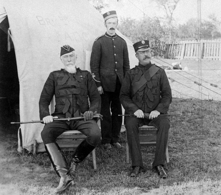
The Commanding Officer, Adjutant and an orderly, ca.1892. Note the Torin cap worn by the Colonel and the two styles of forage cap, bot OR and Officer, worn here. Of interest is the tunic worn by the orderly. Due to limited funds, Militia & Defence could not afford to purchase Guards pattern tunics and provided a quantity of Infantry patern tunics. Some of these were later adapted to double-buttons although the (incorrect) cuffs remained unaltered. MilArt photo archives.

Left, Sergeants forage cap, right, Warrant Officer’s forage cap. Courtesy GGFG Regimental museum
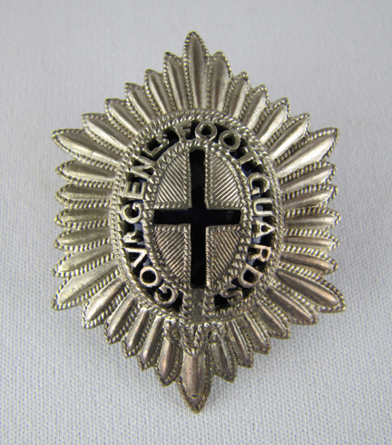
The badge design remained identical for all ranks – a six-pointed star, representing the six extant provinces of Canada in 1872 – although construction differed. The first description of the badges is to be found in the 1898 Queen’s Regulations and Orders which describe the officers’ badge as “A six-pointed star embroidered in silver 1 5/16 inch long by 1 3/8 inch wide. Oval medallion cross in centre of star, with a blue (St. George) cross in the oval”. A smaller, similar but metal badge is authorized for wear on the Torin cap. Other Ranks, who wore the plain Field Service Cap in lieu of the Torin, wore a larger badge as shown below. Perhaps the most interesting point to this badge is the misspelling of the word ‘Governor’.
Often referred to as a Glengarry badge, this pattern was worn by Other ranks on the blue ‘Austrian ppattern’ Field Service Cap. Note the spelling error in ‘Governor’. Author’s collection

Early pattern forage cap. Unlike other infantry regiments were Field Officers display gold piping along the crown, all Guards officers wore this.
The Officers’ forage cap evolved with the introduction of the Staff Pattern of forage cap and the crown became larger. Unlike other Regiments and Corps the GGFG retained a simple band of gold embroidery around the peak for all commissioned ranks, eschewing the Maple Leaf embroidery adopted by Field Officers elsewhere.
An updated Forage Cap, more in keeping with the Staff, or Naval, Pattern introduced in 1904.
In the early 1930s, Headquarters undertook to update the Dress Regulations. The Officers’ cap badge worn at the time was described as ‘In silver, a six-pointed star 1 3/4 inch by 1 3/8 inch; oval medallion in the centre of star, with a blue cross in the oval; cross 10/16 inch by 10/16 inch; and the words “GOVR. GENL, FOOT GUARDS’ placed around the medallion on a blue background.’
GGFG Officers’ cap badge, pierced and enamelled. Author’s collection
While the Adjutant of the GGFG confirmed details with the Coldstream Guards it was discovered that the Officers’ cap badge was not in keeping with British Guards practice. Whereas the GGFG displayed the regimental name, in abbreviated form, in a circle around the St. George cross, every regiment of the British Brigade of Guards displayed the regimental motto. Once this was discovered the Commanding Officer of the GGFG wrote to HQ requesting permission to amend Regulations by removing the regimental name and replacing it with ‘Civitas et Princeps Cura Nostra’ – described in 1932 as representing ‘The state and the head of the State are our charge’.
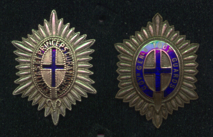
Two patterns of the Officers’ badge. On the right a variant of the badge with Regimental title and on the left a pierced example exhibiting the Regimental motto. Author’s collection
To support this request the Commanding Officer stated that no immediate expense in the provision of dies would be required as the error could only be seen at close distance and that the change could be made when new badges were ordered. In October 1931, the Quartermaster –General agreed to the change and confirmed a few salient points;
– That the blue cross was of enamel and that this was permissible for officers only, and
– The pre-war badge for Warrant Officer and Sergeants featured a pierced cross.
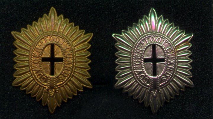
The brass badge appears to have been used prior to the First World Ward and into the 1920s when it was suplanted by the white metal badge. Pre-war only Sergents and Warrant Officers had a pierced cross although postwar all ranks wore the same badge.
The Commanding Officer also suggested that, when new badges were made, that ‘a more effective badge could be obtained by the rays of the star between the points tapering very slightly inwards towards the centre of the badge.’ This design change was finally adopted, but not until well after the Second World War.
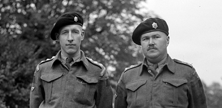
Two GGFG officers. As Officers did not wear collar badges in Service Dress, and the GGFG had no authorized beret badge at this time, the officer on the left has taken a Senior NCO’s collar badge into use.
In addition to cap badges the GGFG have a rich history of shoulder and collar badges as well as rank insignia. The author hopes to present a future article on these.
[i] The number of buttons, within a group, identifies the seniority of (British) Brigade of Guards regiments with the Grenadier Guards wearing ‘single’ buttons, the Coldstream Guards’ buttons worn in pairs, the Scots Guards in groups of three, the Irish Guards in groups of four and the Welsh Guards in groups of five. The GGFG wear theirs in pairs In accordance with their alliance with the Coldstream Guards even though the GGFG are the senior regiment of Foot Guards in Canada.
[ii] These officers were the Medical Officer, Quartermaster and Paymaster. The colour and shape of plume worn on the cocked hat differed for each of these officers.
You can ‘rate’ this article by clicking on thestars (below). You van also leave comments by using the form at the bottom of this page.
by Mark W. Tonner
Two rudimentary devices were used by the Calgary Regiment at Dieppe, which after the raid, would lead to the development of more advanced models of these devices, mounted on the Churchill tank chassis. The two rudimentary devices used by the Calgary Regiment at Dieppe, was the “Oke” flamethrower, mounted in three of the regiments Churchill tanks, and a carpet laying apparatus for forming a trackway that was carried on two bobbins attached to the front of five of the regiment’s Churchill tanks, and was referred to as a “Beach Track Laying Device.”
Background on the Calgary Regiment’s involvement at Dieppe:
Operation Jubilee was the ill‑fated 19 August 1942 combined operations raid carried out against the port of Dieppe. The Calgary Regiment was to land on the main beach at Dieppe, in support of the infantrymen of the 2nd Canadian Division. It is beyond the scope of this article to discuss the details of Operation Jubilee, but the performance and activities of the Churchill tanks of the Calgary Regiment, that were equipped with the “Oke” flamethrower, or the “Beach Track Laying Device,” on 19 August 1942 are relevant. These extracts from the Calgary Regiment’s war diary, Appendix No. 7, dated 20 August 1942, explain the role envisioned for the Calgary Regiment at Dieppe, and briefly, how the regiment faired, from landing to withdrawal. Since few members of the regiment returned from the beaches, it was largely based on plans, radio logs, and observations from those who did not get ashore:
“The general tank plan was that all tanks would land on the main beach at Dieppe in successive waves. “C” Squadron would assist the Essex Scottish in establishing the bridgehead and taking care of the armed trawlers in the harbour. They would then cross to the high ground on the east side of the River D’Arques to dominate the approaches to the east. “B” Squadron was to assist the Royal Hamilton Light Infantry in establishing the right flank of the bridgehead. They would then push inland and take the aerodrome (airfield) at St. Aubin with The Queen’s Own Cameron Highlanders of Canada. “A” Squadron was in reserve and would land later. Once the beachhead was secure, the headquarters of the German 302 Infantry Division at Arques la Battaille would be captured by the Camerons, aided by either “A” or “B” Squadron depending on the tactical situation.
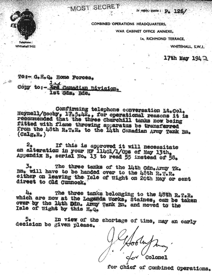
The British Combined Operations Headquarters letter dated 17 May 1942, from the Combined Operations Headquarters to General Headquarters Home Forces, in which it was recommended for operational purposes that the three Churchill tanks fitted with the Oke flame throwing apparatus be transferred from the 48th Battalion, Royal Tank Regiment, to the Calgary Regiment. Source: Authors’ collection.
On the main beach at Dieppe, the main sequence of events was as follows. Despite the heavy bombardment from the sea by naval forces and from the air by bombers, the enemy’s concealed positions in front of the town itself were not destroyed. They were still able to bring intense fire to bear on any point on the main beach from the moment it was assaulted. The first wave of the Calgary’s tanks got ashore successfully, and some of them assaulted the town. Others, however, were not successful in negotiating the sea wall and did not get off the beach. A number of them soon were immobilized. Nevertheless their crews continued to fight their guns, engaging enemy positions with good effect.
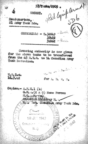
The convening authority for the transfer of T31862, T32049, and T32422, from the 48th Battalion, Royal Tank Regiment, to the Calgary Regiment (who at this time bore the designation of the 14th Canadian Army Tank Battalion (The Calgary Regiment (Tank))). Source: Authors’ collection.
Roads leading into the town were solidly blocked and, in order that the tanks might successfully penetrate into the town, it was essential that these be cleared. The engineers were carrying large quantities of selected explosives for this purpose. Unfortunately, however, the heavy fire that the enemy was still able to bring to bear on the beach caused heavy casualties amongst the sappers (engineers). Despite great courage and determination, they were unable to clear the road blocks. This made it extremely difficult for the tanks to get into the town at all. Consequently the majority of the tanks fought the whole of the engagement from the beach and promenade.
Captain B.G. Purdy, who was commanding No. 8 Troop of “B” Squadron that was specially equipped with flamethrowers, attempted to land as planned on the right of the main beach. However for some unknown reason, his tank went off in very deep water and had to be abandoned immediately. All the tanks that got ashore fought very hard, until they were either put out of action or ran out of ammunition. At about 1225 hours (12:25 P.M.), Major Glenn ordered all personnel to the beach. They were to be ready to abandon the tanks when the boats came in. The fire on the beach at this time had grown very fierce, and casualties in the withdrawing troops were heavy. Only two members of the tank crews who landed managed to get away, and the remainder were either killed or taken prisoner. No. 11, 12, and 14 Troops of “C” Squadron, and the whole of “A” Squadron remained afloat during the operation, lying offshore awaiting orders to go in. About 1300 hours (1:00 P.M.), the order was given to sail back to England.”
The“Oke” flamethrower device:
By the beginning of 1942, under the auspices of the Petroleum Warfare Department and the Ministry of Supply, the British had begun to carry out research and development of tank‑based flamethrowers as a potential offensive weapon. Various prototypes based on the Infantry Tank Mk III, Valentine, were developed and tested, using a two‑wheeled trailer that carried the fuel for the flamethrower apparatus mounted on the tank. After the tests, Major J.M. Oke of the British Army suggested that the jettison fuel container that most tanks were equipped with at the time be used in place of the trailer. The Lagonda Car Company of Feltham, Slough, took up this idea, connecting the jettison fuel container to a Ronson‑type flame projector. They fitted the complete system into a Churchill Mk II tank, which eventually came to be known as the Churchill “Oke.” Having observed trials of Lagonda’s prototype, Lord Louis Mountbatten, the Chief of Combined Operations, pressed for the full development of Lagonda’s concept for operational service.
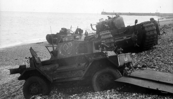
In the centre of this photo from Dieppe, is T68875 Beetle, a Churchill Mk II (Special) of No. 8 Troop, “B” Squadron, The Calgary Regiment, which was fitted with the Oke flame-throwing system. As can be seen, the flame projector was mounted in the front of the tank on the left of the hull gunner’s position and protruded out between the hull machine gun and the left front horn of the tank, the muzzle of which can be seen sticking up above the left track. The tank to the right rear of Beetle, on the shoreline, is T68881 Ringer, a Churchill Mk II, of Regimental Headquarters, The Calgary Regiment. Source: Authors’ collection.
The Churchill “Oke” was basically a Churchill Mk II tank, with a complete Ronson type flamethrower system installed, which consisted of having the rear mounted jettison fuel container connected up to a feed pipe which passed through the left pannier and was itself connected to a flame projector in the front of the tank. The flame projector was mounted in the front of the tank on the left of the hull gunner’s position and protruded out between the left of the hull machine gun and the left front horn of the tank. The flame projector was operated from the hull machine gunner’s seat, and because it was mounted in a fixed position and elevation, the tank had to turn to engage any intended flame target. The basic operation of the flamethrower was that compressed carbon dioxide gas propelled the flame fuel from the jettison fuel container to the flame projector. There, a trigger mechanism opened the pintle valve in the flame projector’s nozzle and projected a jet or pencil of fuel. The carburetor bled petrol into the stream, which was then lit by the action of a spark plug. The range of the Oke flamethrower was 40 to 50 yards.
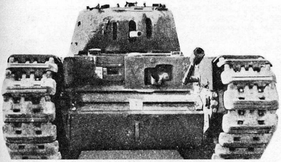
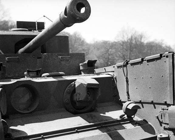
Front viw of the Oke tank. MilArt phto archives
In May 1942, No. 10 Troop, “B” Squadron, 48th Battalion, Royal Tank Regiment, was sent to the Lagonda Works at Staines. There, their three Churchill Mk II tanks (T31862, T32049, and T32422) were fitted with the Oke flame‑throwing system. In a British Combined Operations Headquarters letter dated 17 May 1942, from the Combined Operations Headquarters to General Headquarters Home Forces, it was recommended for operational purposes that the three Churchill tanks fitted with the Oke flame‑throwing apparatus be transferred from the 48th Battalion, Royal Tank Regiment, to The Calgary Regiment. This recommendation was subsequently approved on 18 June 1942, and the transfer took place on 20 June 1942. In Canadian service, these three tanks were designated Churchill Mk II (Special). The Churchill Mk II (Special) tanks were crewed and operated by No. 8 Troop, “B” Squadron of the Calgary Regiment. Although I have been unable to determine exactly when this occurred, sometime before 19 August 1942, the Oke flame‑throwing apparatus in T32422 was removed and fitted into T68875, another Churchill Mk II tank.
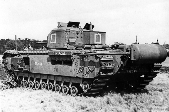
T32049 Tintagel, a Churchill Mk II of No. 10 Troop, “B” Squadron, 48th Battalion, Royal Tank Regiment, fitted with the Oke flame-throwing system. As can be seen in this photo, the rear mounted fuel container is connected up to a feed pipe which passed through the left pannier, which was itself connected to a flame projector in the front of the tank, as explained in the text. T32049 (fitted with the Oke flame-throwing system) was transferred to The Calgary Regiment’s charge on 20 June 1942, where under the name of Boar (No. 8 Troop, “B” Squadron), she was subsequently lost at Dieppe on 19 August 1942. For Dieppe, the rear mounted flame-thrower fuel reservoir, was enclosed within an armoured hexagonal shaped box. Source: Authors’ collection.
The use of the tank mounted “Oke” flamethrower by the Calgary Regiment at Dieppe, although rudimentary in nature, led to development of a more advanced model, of a tank-mounted flamethrower, again based on the Churchill chassis, which came to be known as the Churchill Crocodile, seen pictured here. The flame projector on the Crocodile, replaced the hull mounted machine gun, and had a range of 80 to 120 yards. The armoured fuel trailer, held 400 gallons of flame fuel and enough compressed nitrogen propellant for 80 one second bursts of flame through the flame projector. This trailer was connected to the tank by a three-way armoured coupling and could be jettisoned from within the tank if necessary. Source: Authors’ collection.
All three of these Churchill Mk II (Special) tanks T31862 Bull, T32049 Boar, and T68875 Beetle equipped with the Oke flame‑throwing apparatus took part in the raid at Dieppe on 19 August 1942. They were all destroyed before they could get into action. All three were carried on Tank Landing Craft 3 (No. 159):
– T31862 Bull was the troop commander’s (Captain B.G. Purdy) tank and was launched prematurely and drowned in 10 feet of water approximately 100 yards offshore.
– T32049 Boar, commanded by Sergeant J. Sullivan, in making a heavy landing from Tank Landing Craft 3, knocked her flamethrower fuel reservoir off her rear plate, but managed to cross the beach and get onto the promenade in the area of the Cassino. She remained mobile throughout the morning before being ordered back to the beach to cover the withdrawal. Once back on the shoreline, she was immobilized and acted as a pillbox.
– T68875 Beetle, commanded by Lieutenant G.L. Drysdale, also landing heavy, broke a track pin on her right track and remained immobilized on the shoreline, at the eastern end of Red Beach, also acting as a pillbox. Although the Churchill mounted, Oke flamethrower was rudimentary, by their presence at Dieppe, it is considered to be the first time that a British‑designed tank flamethrower took part in battle.
A closeup of the flame projector, which replaced the hull mounted machine gun, on the Churchill Crocodile. Source: Authors’ collection.
The Beach Track Laying Device:
The main beach at Dieppe, over which the Churchill tanks of the Calgary Regiment were to land, was entirely composed of rounded and oblong chert rocks which range from one to six inches in diameter, and was resistant to cracking or breaking. Tidal action, leave most of these chert rocks eventually resting on the beach surface at an angle of about 15 to 20 degrees. With these rocks being many metres in depth, vehicles would not be able to dig down to a solid base for traction. If a tracked or wheeled vehicle tried to climb up this slope, it would immediately dig itself down, and in the case of tracked vehicles, the strain of these chert rocks caught up between the drive sprocket and track, would cause the pins that held the track links together, to break, thus immobilizing the tank.
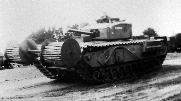
Another view of the “Beach Track Laying Device,” during the trails conducted by the Combined Operations Experimental Establishment. Note the position of the roll of chespaling, which was set approximately 24-inches, in front of the track. Source: MilAt photo archives.
Originally, to alleviate the foreseen problem of these chert rocks, it was planned to have four‑man teams of Royal Canadian Engineers, carried in each of the six Tank Landing Craft, that were scheduled to land in the first wave, who would run out ahead of the lead tanks, and roll out bundles of chespaling tracks. Chespaling was flexible roll fencing similar to wood slat snow fencing, but made with tough split slats made of chestnut. It was thought that by using chespaling, both wheeled and tracked vehicles would be able to get over the worst conditions of the chert rocks on the beach. Each of these bundles weighed approximately 250 pounds, were 25 feet long and could be wired together to form a continuous track, and could be moved around by the engineers to suit the later waves of incoming Tank Landing Craft. It was also found that chespaling enabled a tank to climb a 28-inch high wall.
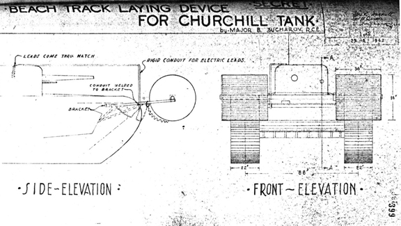
A sketch of Major Sucharov’s design for the “Beach Track Laying Device,” dated 25 August 1942. Note the location of the rigid conduit, which had to be added for the protection of the wiring for the electrically fired small explosive charges, that released the rolls, and for those that jettisoned the whole device, and its path, back to the turret. Source: R.C. Harley.
Because of the weight of these chespaling bundles, and taking into account the probability of high casualties amongst the four‑man teams of Royal Canadian Engineers, from enemy fire, it was decided that an alternate method of laying out these bundles of chespaling tracks, ahead of the leading tanks of the first wave, be developed. Major B. Sucharov, an officer of the Royal Canadian Engineers (who commanded the engineers Beach Assault Party at Dieppe), was assigned to develop a device to enable the tanks, not only to get over the beach on landing, but to get over the seawall that separated the beach from the Promenade.
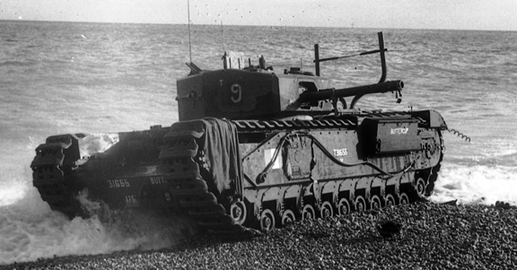
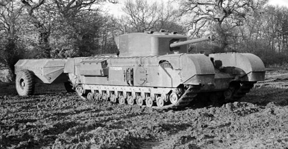
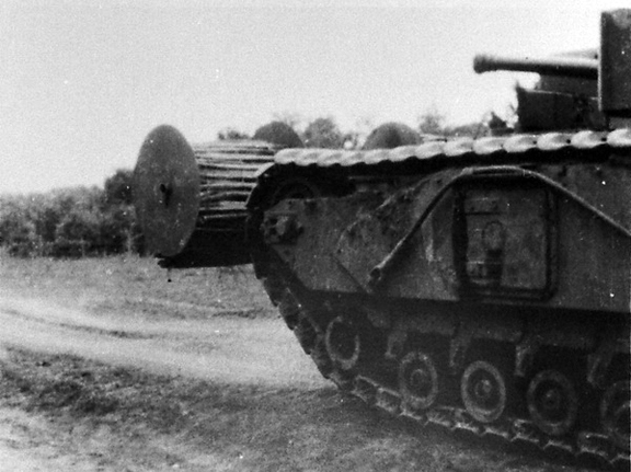
T31655 Buttercup, a Churchill Mk III of No. 9 Troop “B” Squadron, The Calgary Regiment, commanded by Sergeant J.D. Morrison, also one of five Churchill tanks of the regiment that was fitted with the “Beach Track Laying Device,” for the Dieppe raid. Having successfully landed and laid its chespaling and, having crossed the beach, wire, and seawall, it successfully jettisoned its beach track laying device, whereupon it engaged enemy targets on the west headland and in seafront buildings to the west of the Casino. Later, it returned to the beach below the Casino, where it took up a position on the water’s edge. It could not be destroyed by its crew prior to their withdrawal, due to the number of infantry wounded who had sought shelter from enemy fire on its seaward side. Note that there are no remnants of the beach track laying device, on her front, it having been jettisoned successfully. Source: Authors’ collection.
To this end, Major Sucharov came up with a carpet‑laying device using chespaling. He designed an apparatus that carried two separate rolls of chespaling, one for each tank track, which were suspended, about 24‑inches in front of each track, on a spindle that was supported by two short brackets above the front horns of the tank. The apparatus was mounted low enough to allow the tank commander a clear field of vision, and gave a clear field of fire for the turret mounted main armament and co-axial machine gun. On the inside and outside of each roll of chespaling, there was provided a 14-gauge metal disc shield, 3 feet in diameter to prevent the chespaling from fouling the brackets and spindle. Each roll of chespaling was 3 feet wide and 25 to 30 feet in length, with weighted ends that upon release, fell to the ground with the tank tracks themselves feeding out the rolls as the tank moved forward. The release of these rolls was controlled from the turret by means of an electrically fired small explosive charge. After use, the whole apparatus could be jettisoned by a small explosive charge, electrically set off from inside the turret.
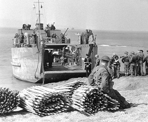
From the Yukon series of exercises that were held at the tiny fishing harbour of West Bay on the coast near Bridport, Dorset, bundles of chespaling, used for laying a track to enable disembarking tanks to cross the beach, can be seen on the left. These bundles weighed approximately 250 pounds, were 25 feet long. Source: Authors’ collection.
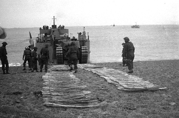
Churchill tanks of The Calgary Regiment taking part in a series of exercises (Yukon I, 11/12 and Yukon II, 22/23 June 1942) that were held at the tiny fishing harbour of West Bay on the coast near Bridport, Dorset. In this photo, soldiers of the Royal Canadian Engineers, have rolled out bundles of chespaling tracks to enable the disembarking tanks to cross the beach. Source: Authors’ collection.
– T31124R Chief, a Churchill Mk I, carried in Tank Landing Craft 1 (No. 145), commanded by the Officer Commanding “C” Squadron, Major A. Glenn, prematurely laid its chespaling, and having jettisoned the beach track laying device, remained on the beach. For a time, Major Glenn kept his tank in a position from which he could observe the promenade and both flanks of the beach, when not obscured by smoke. After moving down the beach to the area in front of the Cassino, T31124R (Chief), returned the way it had came, and took up a position at the western end of the beached Tank Landing Craft 3 (No. 159) and turned broadside to the enemy, to protect the men sheltering behind the beached Tank Landing Craft.
– T68173 Cougar, a Churchill Mk III, carried in Tank Landing Craft 2 (No. 127), No. 13 Troop, “C” Squadron, the Troop Leader’s tank, commanded by Lieutenant T.R. Cornett, successfully crossed the beach and having laid its chespaling, crossed the seawall onto the Promenade, having only jettisoned part of its beach track laying device. Whereupon, after turning to the west, it was immediately hit by a 75‑millimetre round that jammed its turret. After this, it was only able to engage the tobacco factory with its 6‑pounder main armament from its position on the Promenade. Eventually, after having broken one track and having the other blown by enemy fire, it was destroyed by its crew, prior to their retiring back to the beach.
– T31135R Burns, a Churchill Mk I, carried in Tank Landing Craft 4 (No. 126), commanded by the Officer Commanding “B” Squadron, Major C.E. Page, removed its beach track laying device prior to landing, because it had been damaged. Having landed, Burns started to advance across the beach, but found its path obstructed by a tank trap consisting of a trench dug along the front of the esplanade wall. Upon attempting to avoid this obstacle, the tank’s right track was broken by enemy fire, which caused Burns, to be pulled into this ditch by the forward momentum of her left track, leaving her immobilized pointing downwards and unable to use its armament against enemy targets.
– T31655 Buttercup, a Churchill Mk III, carried in Tank Landing Craft 5 (No. 121), No. 9 Troop, “B” Squadron, the Troop Sergeant’s tank, commanded by Sergeant J.D. Morrison, successfully laid its chespaling and, having crossed the beach, wire, and seawall, jettisoned its beach track laying device, whereupon it engaged enemy targets on the west headland and in seafront buildings to the west of the Casino. Later, it returned to the beach below the Casino, where it took up a position on the water’s edge. It could not be destroyed by its crew prior to their withdrawal due to the number of infantry wounded who had sought shelter from enemy fire on its seaward side.
– T68557R Bob, a Churchill Mk III, carried in Tank Landing Craft 6 (No. 163), No. 6 Troop “B” Squadron, the Troop Leader’s tank, commanded by Lieutenant J.H. Dunlop, removed its beach track laying device prior to landing, also because of damage. It landed and successfully crossed the seawall near the Casino, where it engaged enemy targets with the 6‑pounder main armament until eventually returning to the beach, where it took up a position on the water’s edge to cover the withdrawal of the infantry.
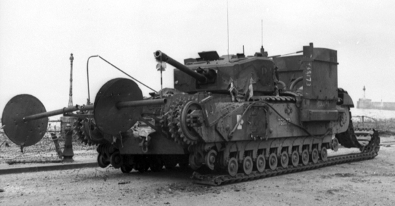
T68173 Cougar, a Churchill Mk III of No. 13 Troop, “C” Squadron, The Calgary Regiment, one of the five tanks fitted with the “Beach Track Laying Device,” for the landings at Dieppe on 19 August 1942. Having only jettisoned part of its beach track laying device, the remains of it are clearly visible on her front. Notice how the two short brackets carried the spindle, and that the inside and outside 3 foot diameter, 14 gauge metal disc shields, that prevented the chespaling from fouling the brackets and spindle, have closed up on themselves. Note also, the remains of the rigid conduit, on her right side, that had to be added for the protection of the wiring for the electrically fired small explosive charges, that released the rolls, and for those that jettisoned the whole device. Source: Authors’ collection.
The value of these tanks fitted with the “Beach Track Laying Device,” at Dieppe can be seen from the following extract from Report No. 98 dated 15 July 1943, written by the Historical Officer, Canadian Military Headquarters:
“It was reported and believed at the time that the sea‑wall forming the seaward edge of the Promenade had proved a serious obstacle to the tanks and was responsible for the failure of many of them to get on. Close analysis of the facts reveals that this was not the case. The sea‑wall at most points rose not more than two feet above the shingle. Experiments had shown that the best way of getting tanks over such an obstacle was to lay tracks of chestnut paling on the beach to give them traction, and Canadian engineers had developed a track‑laying device by which rolls of paling could be carried on the front of tanks and laid when required. This device worked well. The first tank to leave the first craft to touch down laid its paling and with its assistance easily crossed the wall; the two tanks behind followed in its path and also mounted the wall.”
In 1943, Major Sucharov was subsequently made a member of the Order of the British Empire, his citation for which reads:
“The initiative, drive and zeal of this officer have been outstanding since he landed in England in February 1940. He displayed great leadership and tireless energy in the engineer preparations for the Dieppe operations and experimented with new design of high explosives for offensive demolitions. He personally designed and produced the official attachments which enabled the tanks to overcome the shingle beaches and surmount the sea wall at Dieppe and during operations displayed the highest qualities of courage and resolution under heavy fire.” [i]
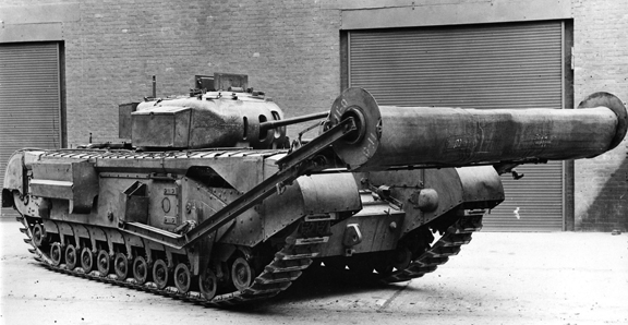
As mentioned in the text, the use of the “Beach Track Laying Device” at Dieppe, led to the development and production of various forms of mat layers to assist the passage of both wheeled and armoured vehicles over soft ground. The Bobbin Mk I and Bobbin Mk II, were two types of these mat layers that were developed. This photo shows a Bobbin Mk I, which carried a 9-foot 11-inch wide canvas mat on a spindle supported by short movable arms above the front horns of the tank, fitted to the front of a reworked Churchill Mk II tank. Source: Authors’ collection.
After Dieppe, Major Sucharov’s concept of the “Beach Track Laying Device,” was sent to the Combined Operations Experimental Establishment, Appledore, Devon, for further evaluation and trails. These trails were conducted throughout the rest of 1942, and into 1943, but the device itself was never developed for operational use.
The use of the “Oke” flamethrower and the “Beach Track Laying Device,” by the Calgary Regiment during the raid at Dieppe, was the first time that these equipments had been used in battle. Although rudimentary in nature, both concepts were considered successful, leading to development of more advanced models, again based on the Churchill chassis. In the case of the three Churchill Mk II (Special) tanks with the Oke flamethrower, the concept of a tank‑mounted flamethrower led to the development and production of the Churchill Crocodile flamethrower. By May 1945, a total of eight hundred Crocodile units had been built.
The use of the “Beach Track Laying Device,” led to the development and production of various Armoured Vehicles Royal Engineers that were based on the Churchill chassis. Some of these were fitted with various forms of mat layers to assist the passage of both wheeled and armoured vehicles over soft ground. Two types of these mat layers were the Churchill Armoured Vehicle Royal Engineers (AVRE) fitted with either the Bobbin Mk I or Mk II. The short arms on the Mk I were movable, while those on the Mk II were fixed. Another Churchill Armoured Vehicle Royal Engineers was fitted with the “Log Carpet Device,” which consisted of a carpet made up of one hundred 14‑foot long by 6‑inch diameter logs, which were bound together with wire rope. This log carpet was carried in a removable steel frame above the superstructure of the Armoured Vehicle Royal Engineers, and was released over the front of the vehicle by means of a small explosive charge.
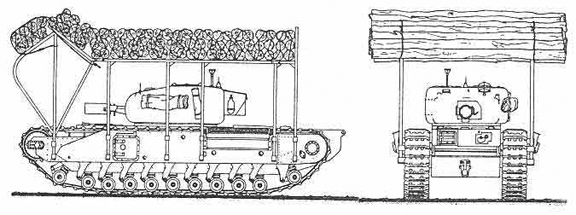
A diagram of the Churchill Armoured Vehicle Royal Engineers that was fitted with the “Log Carpet Device,” which consisted of a carpet made up of one hundred 14 foot long by 6 inch diameter logs, which were bound together with wire rope. This log carpet was carried in a removable steel frame above the superstructure of the Armoured Vehicle Royal Engineers, and was released over the front of the vehicle by means of a small explosive charge. Source: Authors’ collection.
Note: In my two previous books [ii]dealing with the Churchill tank in Canadian service, I erroneously stated, that the rudimentary apparatus for forming a trackway carried on a bobbin on the front hulls, of some of the Calgary Regiment tanks at Dieppe, was a carpet laying device. This device, I had described as consisting of a single spindle supported by short arms above the front horns of the tank, that carried a mat of chespaling, that was 9 feet 11-inches wide by 25 to 30 feet long. Having recently been made aware of new information, I can now say, that I have set the record straight.
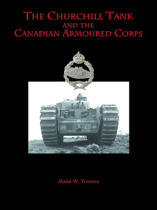
For more information on the Churchill tank and its use by the Canadian Army is available in the author’s book, published by Service Publications. (www.servicepub.com)
You can ‘rate’ this post by clicking on the stars (below) and you can leave comments using the form at the bottom of this page.
[i]. Courage & Service, Second World War Awards to Canadians, by John Blatherwick & Hugh Halliday, 2006, Service Publications; Ottawa, Ontario, Canada. ISBN 1‑894581‑22‑9
[ii]. The Churchill in Canadian Service (Canadian Weapons of War Series), 2010, Service Publications; Ottawa, Ontario, Canada. ISBN 978‑1‑894581‑67‑7, and The Churchill Tank and the Canadian Armoured Corps, 2011, Service Publications; Ottawa, Ontario, Canada. ISBN 978‑1‑894581‑66‑0
by Mark W. Tonner
The war diary of 1st Canadian Army Tank Brigade Heavy Support Company for June 1942 described the Carrier, Churchill, 3-inch Gun Mk I as, “…a temporary expedient to deal with super heavy enemy tanks, should such be used until the 17-pounder anti-tank gun is issued.” This Churchill variant more or less came into being because the British needed to find a weapon that would be powerful enough to defeat German tanks in the event of an invasion. As an expedient measure, it was a quick and effective means of transporting the heaviest possible anti-tank gun on some sort of tank chassis. The British chose the 3-inch, 20-hundredweight anti-aircraft gun to fulfil this role, opting to install it in a limited traverse mount on the chassis of the Churchill Mk III tank. The idea of mounting the 3-inch anti-aircraft gun on a tank chassis for use in the anti-tank role, was first raised in March 1941 at a meeting of the British Director General of Tanks and Transport committee. Then, the committee was advised that the British Defence Committee had requested that the 3-inch anti-aircraft gun should be carried in some tanks, as a temporary measure until sufficient stocks of the 6-pounder anti-tank gun became available. By 1940, the 3-inch, 20-hundredweight anti-aircraft gun was being replaced in the British Army by the new 3.7-inch anti-aircraft gun, so a ready stock of the 3-inch anti-aircraft guns were available.

The initial contract card for Contract No. T.2787, dated 25 July 1941, for 100 (later amended to 50) Tanks, A22, “Special Type” (Carrier, Churchill, 3-inch Gun, Mk I), that was placed with Vauxhall Motors Ltd. Also recorded on the card, is the block of Census Numbers assigned , S31273 – S31321, along with the completion date of 2 November 1942. Source: author’s collection.
Within two weeks of the Director General of Tanks and Transport committee meeting, the British War Cabinet approved mounting the 3-inch anti-aircraft gun on a tank chassis, followed a week later by the Director General of Tanks and Transport informing the Defence Committee that the Churchill chassis was the best choice. Vauxhall Motors Ltd., of Luton, Bedfordshire, were asked to design the vehicle and, by the end of April 1941, had more or less completed the general arrangement drawings. Early in July 1941, Vauxhall had completed a wooden mock-up and the Department of Tank Design issued them a contract (Contract No. T.2787) for 100 Tanks, A22, “Special Type” (Carrier, Churchill, 3-inch Gun, Mk I) on 25 July. Having completed the pilot model, Vauxhall sub-contracted (Contract No. T.11614) out the assembly to Beyer, Peacock & Company, Ltd., of Manchester. In December 1941, the Director General of Tank Supply reduced the order to 24 vehicles, but subsequently increased this to 49 in January 1942. Production began in May 1942 but, with the threat of invasion fading away, the average output was one per week. The contract was completed on 2 November 1942, and the tanks were assigned the Census Numbers S31273 – S31321.

The contract card for Contract No. T.11614, under which Vauxhall sub-contracted out the assembly to Beyer, Peacock & Company, Ltd of Manchester, for 49 Tanks, A22, “Special Type” (Carrier, Churchill, 3-inch Gun, Mk I), with reference to the initial Contract No. T.2787, again showing the block of Census Numbers assigned , S31273 – S31321, along with the completion date of 2 November 1942. Source: author’s collection.
In appearance, the Carrier, Churchill, 3-inch Gun Mk I resembled a standard Churchill Mk III tank, but without the turret. Instead, it had a large fixed box-type superstructure which housed the main fighting compartment, with the gun mounted low down at the front, to the left of the driver’s position. Each vertical side plate of the superstructure had a circular pistol port. This port was hingeless and had a rapid opening and closing control. Access was either through the hinged door fitted in the rear vertical plate, or through a hinged double door hatch fitted in the roof, which also acted as the commander’s cupola, which was rotatable and was equipped with two periscopes. Each side plate had a large stowage bin, one mounted forward on the left and the other mounted to the rear on the right. A No. 33 sighting telescope was located in a fabricated bracket, in an open aperture in the left upper corner of the front plate, in a position convenient to the gun layer, directly above the driver’s visor. The hull sides retained the square escape doors, as on the Churchill Mk III, the tracks were fully covered and the engine air intake louvres (on the hull sides) had the opening on top.
A No. 19 wireless (radio) set was housed in the main fighting compartment. This set included an “A” set for general use, a “B” set for short range inter-tank work at troop level, and an intercommunication unit for the crew, so arranged that each member could establish contact with any one of the others. Adequate provision was made for the stowage of both ammunition and equipment, both within the interior and on the exterior of the vehicle. A comprehensive tool kit was provided with the vehicle so that every operation listed in the routine maintenance section of the Carrier, Churchill, 3-inch Gun Mk I Service Instruction Book (August 1942) could be efficiently carried out.

An image of the Carrier, Churchill, 3-inch Gun Mk I, showing the front of the large fixed box-type superstructure, that replaced the turret. Note the open aperture in the left upper corner of the front plate directly above the driver’s aperture, for the No. 33 sighting telescope and the location of the 3-inch, 20-hundredweight high velocity anti-aircraft gun, in the front plate. Also visible, on the turret roof to the right of the open aperture for the No. 33 sighting telescope, is the external triple-vane sight that was provided for the crew commander, so that he could bring the driver into rough alignment with the target. Source: author’s collection.
The commander’s position was located midway along the right side of the superstructure, inside the roof hatch. Directly in front of the commander was the gun layer’s position with the loader on his left. The driver was located in front of the gun layer, in the normal driver’s location for a Churchill tank. Since the 3-inch 20-hundredweight gun was mounted in a fixed turret, it could only be used with open sights. The commander was also provided with an external triple sighting vane, the outside vanes of which were painted white and corresponded to the free 5-degrees in either direction of the gun, so that he could bring the driver into line with the target. If a target appeared anywhere within this vane, when sighted through the commander’s periscope, the gun was then able to be layed on that target by its own traverse and without movement of the vehicle, provided, that the gun was at its central traverse point at the outset. Because the mounting had only 5-degrees of traverse, either side of the centre line, the driver had to be in place, with engine running, in order that he could traverse the Carrier into rough alignment with the target. To assist him in knowing when the gun was reaching the limit of its traverse, he had a traverse indicator alongside his visor. The gun could only be fired while the vehicle was stationary. Because of its heavy weight, the gun had to be locked at full elevation when the Carrier was travelling to prevent damage to the gun.

In this right side view, it can be seen, that in appearance, the Carrier, Churchill, 3-inch Gun Mk I resembled a standard Churchill Mk III tank, but without the turret. Note the large fixed box-type superstructure, which housed the main fighting compartment, with the gun mounted low down at the front to the left of the driver’s position. As can be seen, the hull sides retained the square escape doors (with circular pistol port) of the Churchill Mk III, the tracks were fully covered, and the engine air intake louvres (on the hull sides) had the opening on top. The anti-aircraft mounting for the .303-inch Bren (Mk I) machine gun, can be seen stowed just above the circular pistol port in the vertical side plate of the superstructure. Also, of note, in this photo, the 3-inch gun, is at full elevation, the position it would be locked in when the Carrier was travelling, in order to prevent damage to the gun. Source: author’s collection.
During an engagement, the commander used his external sighting vane to direct the driver to bring the Carrier into rough line with the target. The gun layer then used his limited traverse to lay the gun on the target. Once laid on the target, the gun was fired using a strap with one end connected to the trigger release mechanism, and the rest of the strap forming a harness for the gun layer, who fired the gun by a body movement. The gun layer was provided with two hand wheels, one to elevate the gun, and the other to traverse the gun. Loading and unloading was carried out by hand. A round of armoured precising ammunition weighed 12½ lbs. When firing, the instruction book stated that the rear door had to be open and the engine held at 1,500 revolutions per minute to provide adequate ventilation for the crew. However, it was found during trials that by redesigning the two electric fans situated at the rear of the fighting compartment to extract air at 900 cubic feet per minute, firing could be carried out with the Carrier completely closed down.

In this view of S31273R, details of the left side of the Carrier, Churchill, 3-inch Gun Mk I, can be seen. The external triple-vane sight, which was provided for the crew commander, is clearly visible on the turret roof. Source: author’s collection.
On 8 April 1942, Headquarters 1st Canadian Army Tank Brigade received a letter indicating that General Headquarters, Home Forces had recommended to the War Office that several army tank brigades, including 1st Canadian Army Tank Brigade, each be issued with nine of the Carrier, Churchill, 3-inch Gun, Mk I. Each brigade would form three troops of three Carriers each, with one troop being attached to each army tank battalion. No additional personnel were authorized and the Carrier would be carried as extra to the war establishment of each army tank battalion. On 23 April, Headquarters, 1st Canadian Corps confirmed to 1st Canadian Army Tank Brigade, that they would receive nine Carriers as a temporary expedient to deal with super heavy enemy tanks until the 17-pounder anti-tank gun was issued. The brigade commander (Brigadier R.A. Wyman) 1st Canadian Army Tank Brigade was asked for his comments on the manning and distribution of the Carriers in his brigade.

In this external stowage sketch, the circular pistol port, in both the square escape door, and the vertical side plate of the superstructure, can be seen, along with the hinged door fitted in the rear vertical plate, and the hinged double door hatch fitted in the roof, which acted as the commander’s cupola, forward of which is located the external triple-vane sight that was provided for the crew commander. Note the external auxiliary fuel tank, on the rear plate, which carried an additional 32.5 gallons of fuel. This auxiliary tank was connected to the main fuel system, but could be jettisoned from the tank in an emergency. Source: author’s collection.
Brigadier Wyman replied on 29 April 1942, proposing a distribution of three Carriers per battalion, as a heavy anti-tank troop. He also suggested that these carriers be manned by the personnel from the “Special Increment” of four officers and seventy-seven other ranks authorized for each tank battalion. This “Special Increment”for each tank battalion, which was authorized under Canadian Military Headquarters Administration Order No. 68, dated 5 April 1942, was a fixed scale addition of personnel held by No. 2 Canadian Armoured Corps Reinforcement Unit, to the authorized War Establishment strength for each of the tank battalions of 1st Canadian Army Tank Brigade. On 19 May, Headquarters, 1st Canadian Corps directed that the Special Increment would not be used to man these carriers, but that an ad-hoc unit would be formed. This would be known as the 1st Canadian Army Tank Brigade Heavy Support Company, and Brigadier Wyman was to submit a proposed war establishment at once. This was submitted to the corps headquarters on 22 May. In it, Brigadier Wyman proposed to establish a company headquarters capable of administering three self-contained troops, in much the same manner as an anti-tank regiment headquarters functioned in an infantry division. Each troop would have three Carriers and could be assigned to an army tank battalion. The proposed personnel strength of the Company was ninety-seven all ranks, twenty-eight in company headquarters, and twenty-three in each of the three troops.
This was formalized in Canadian Military Headquarters Administration Order No. 167, with effect from 24 June 1942, under the authority of National Defence Headquarters Cable GSD 602. This granted approval for the formation of the 1st Canadian Army Tank Brigade Heavy Support Company, under the command of Headquarters, 1st Canadian Army Tank Brigade, on a field return basis, from field and reinforcement personnel. The war establishment for “A Canadian Army Tank Brigade Heavy Support Company” was also authorized under the authority of GSD 602, with effect from 24 June 1942. The war establishment, as authorized, was exactly the same as the proposed one that Brigadier Wyman had submitted to Headquarters, 1st Canadian Corps on 22 May 1942.

An interior stowage sketch, looking forward from the rear of the fighting compartment. Note the location of the No. 19 wireless (radio) set, in the upper-left hand corner of the fighting compartment. Source: author’s collection.
On 30 June 1942, Headquarters, 1st Canadian Army Tank Brigade, ordered the three tank regiments (on 15 May 1942 the tank battalions of the brigade had been redesignated tank regiments) of the brigade to facilitate the rapid formation of the 1st Canadian Army Tank Brigade Heavy Support Company and to make it an efficient fighting unit as quickly as possible. To that end, it had been decided that all personnel would be drawn from the units of the brigade. By 3 July 1942, each regiment was to nominate one officer to be a troop commander and to supply the personnel for one complete troop as selected by the troop commander. Each regiment was also to submit recommendations for non-commissioned officers to fill the positions of squadron sergeant-major, squadron quartermaster sergeant, and squadron mechanist sergeant in the company headquarters of the new formation. On 1 July 1942, the brigade commander selected Captain G.S.G. Jones of The Three Rivers Regiment as the first officer commanding, with Captain D.C. Matthews of Headquarters, 1st Canadian Army Tank Brigade, as second-in-command of the heavy support company. Both of these officers were later succeeded upon posting away from the unit to other duties in the fall of 1942, by Major C.H. Humber and Captain J.D. Pearson, respectively.
Brigadier Wyman and Captain Jones met at Headquarters, 1st Canadian Army Tank Brigade on 15 July to discuss various subjects in relation to the formation and organization of the heavy support company, such as training, and vehicle allotment. The point of standardizing the unit cap badge was brought up and it was agreed that the Canadian Armoured Corps cap badge would be adopted for wear. It was also agreed that the vehicles of the 1st Canadian Army Tank Brigade Heavy Support Company, would adopt the Arm of Service marking of Headquarters, 1st Canadian Army Tank Brigade (serial 171) along with the 1st Canadian Army Tank Brigade formation sign of a Gold or Yellow Maple Leaf centred on an 8-inch wide by 10-inch high black background square, with a black left facing image of a Ram superimposed centrally on the maple leaf. Effective 31 October 1942, the formation sign of the 1st Canadian Army Tank Brigade was changed to a Gold or Yellow Maple Leaf superimposed centrally on an 8-inch wide by 10-inch high background square of three equally horizontally divided strips of black-over-red-over-black.

An interior stowage sketch, looking to the rear of the fighting compartment. Note the stowage for the 16 high explosive rounds, in the two bins which were painted red, and the stowage of armour piercing rounds, on the left and right, and the loader’s seat, in front of the left-hand high explosive round been. Source: author’s collection.
The headquarters of the 1st Canadian Army Tank Brigade Heavy Support Company was established at Warninglid, Haywards Heath, Sussex, being co-located with that of 1st Canadian Army Tank Brigade Headquarters Squadron. During the rest of July, the new formation was organized and arrangements made for unit personnel to attend courses at various schools and training establishments. Also, a location was sought that could hold the new formation, and on 27 July, Ovingdean School, Ovingdean, Sussex, became the permanent accommodation for the 1st Canadian Army Tank Brigade Heavy Support Company. Starting in August 1942, the gunnery wing of the British Army Armoured Fighting Vehicle School at Lulworth Camp, Dorset, began to run a one-week course on the Carrier for unit personnel. Some were also sent to attend courses on the Carrier at the Driving & Maintenance Wing of the Armoured Fighting Vehicle School at Bovington Camp, Dorset. Unit fitters, driver-mechanics, motor-mechanics and storemen were sent off on courses at Royal Army Ordnance Corps schools at Bordon Camp, Hampshire and at Canterbury, Kent.
It was not until September 1942 that the Carrier began to be issued to the 1st Canadian Army Tank Brigade Heavy Support Company. By 19 September, they had been issued five equipments, all based on reworked Churchill Mk III tanks. One problem that the crews encountered with these Carriers, was that they had a tendency to throw their tracks when turning at speeds of 10 miles-per-hour or higher. In October 1942, the company was redesignated a squadron (1st Canadian Army Tank Brigade Heavy Support Squadron), so as to conform to Canadian Armoured Corps nomenclature. By 10 October, the squadron had been issued three more equipments, bringing their holdings up to a total of eight, and by 7 November the squadron held a total of ten (one surplus) (S31274R, S31275R, S31276R, S31277R, S31278R, S31279R, S31280R, S31281R, S31283R, and S31284R). The surplus Carrier remained with the unit until 23 January 1943, when one Carrier (S31277R), having been in workshop since 26 December 1942, was turned into No. 1 Sub-Depot of No. 1 Canadian Base Ordnance Depot, Bordon Camp, Hampshire.
On 15 February 1943, Headquarters, 1st Canadian Corps ordered that 1st Canadian Army Tank Brigade Heavy Support Squadron was to be broken up immediately. Headquarters, 1st Canadian Army Tank Brigade confirmed this on 21 February and by 4 March 1943, having returned all vehicles and stores, and with all personnel of the squadron having been dispersed, the squadron was disbanded.
Characteristics of the Carrier, Churchill 3-inch Gun Mk I
Crew: four (commander, gun layer, loader, driver)
- Weight: 39 tons
- Length: 26 feet 1 inch (including gun)
- Width: 10 feet 8 inches (with air intake louvres on sides)
- Height: 9 feet 1 inch
- Length of tracks on ground: 12 feet 8 inches
- Width over tracks: 9 feet 1 inch
- Clearance under hull: 1 foot 9 inches
- Armour thickness: Superstructure: frontal plate (basically an extension of the vertical driver’s visor plate) 89 millimetres
- Side plates: 76 millimetres
- Rear plate: 76 millimetres
- Roof plate: 15 millimetres
- Road speed: 15½ mph
- Cross country speed: 8 mph (approximately)
- Engine: 12 cylinder Vauxhall Bedford twin-six 350 horsepower
- Weight of engine: 3,376 lbs (dry)
- Fording depth: 3 feet 4 inches (without preparation)
- Trench crossing ability: 10 feet
- Vertical obstacle capacity: 2 feet 6 inches
- Turret: Fixed
- Main armament: 3-inch, 20-hundredweight – high velocity anti-aircraft gun
- Elevation main armament: minus 10-degrees to plus 15-degrees
- Traverse main armament: 5-degrees either side of the centre line
- Muzzle velocity main armament: 2000 feet per second (able to penetrate 100 millimetres of armour at 200 yards)
- Ammunition stowage: 49 rounds of armour piercing and 16 rounds of high explosive
Remarks: Each tank was also supplied with one .303-inch Bren (Mk I) machine gun with an anti-aircraft mounting and six 100-round drum type magazines, and two .45 calibre Thompson Sub-Machine Guns with thirty-two 20 box type magazines each, and six Grenades No. 36 Mk I
If you enjoyed this article please ‘rate’ it using the stars below. You may also leave a comment.

For more information on the Churchill tank and its use by the Canadian Army is available in the author’s book, published by Service Publications at www.servicepub.com.
By Clive M. Law
Even before the Second World War came to a successful conclusion the British, Canadian and American armies were giving serious thought to the uniform to be worn postwar. Although both Britain and Canada agreed that Battledress, as well as a tropical uniform, would be retained – with minor changes to incorporate improvements suggested during the war – there remained a focus on a No.1 Dress uniform. This focus reflected the belief that Full Dress and Mess Dress were prewar anachronisms. In fact, the wear of both of these orders of dress had been prohibited at the outbreak of war.
A 1946-dated report, prepared by the Canadian Army’s Master-General of the Ordnance (MGO) stated:
“The trend in proposed orders of dress for the United States Army appears to follow closely the British trend. It is intended that there will be one order of dress for all ranks, namely Battledress, which is to be manufactured from worsted olive drab serge. The same material is to be used for all ranks except that officers may make use of superfine tailoring at their own expense. In addition the United States Army proposes a new walking-out or regimental uniform in blue. It is trimmed with a neutral colour (probably a greyish fawn) to simplify provision by the elimination of a great number of regimental or corps colours in the trim. The open collar conventional style with shirt and tie is definitely favoured. A cloth belt is to be worn and peak service cap of the same colour as the uniform. The uniform is to be manufactured of worsted serge or Barathea material of blue.”
“The uniform has not yet been adopted but six or seven departmental models are being displayed to the United States troops in all theatres to obtain their reaction as a guide to design and colour (of blue) and colour of trim (chevrons). The designs being shown have conventional collars, piqued lapels, are semi form fitting with a plain back, full blade, normal waist, and flat hips. They have two breast patched pockets, pleated with three pointed flaps, button and buttonhole throat. The side pockets are cut in, inside hanging with square flaps, button and buttonhole throat.”
Following communications with the British Army, the MGO reported:
“For these purposes a new uniform is proposed, provisionally known as No I dress, normally dark indigo blue in colour, with badges and minor variations of piping etc according to regimental tradition. This uniform is intended for the full-time Army and the scale of issue to be one suit per man. It will not be issued to the Territorial Army. The details are still to be decided but in general it consists of a jacket, and trousers of modified civilian cut with the traditional coloured stripes. A forage cap and coloured girdle (Sam Browne belt for officers) is proposed for formal occasions and a beret and cloth belt, both normally blue, for walking out. Metal buttons, small patrol size and metal badges are retained, but efforts are being made to find a material which does not require cleaning. Black polished boots are prescribed for duty wear and black shoes (with dark blue socks) for walking out.”

The British proposed uniform (worn here by a Canadian model) was a recycling of the prewar blue serge uniform but with the addition of regimental piping to the shoulder straps.
“This uniform is intended for all units except the Scottish Regiments, but for the Rifle Regiments the colour will be rifle green (black in the case of Kings Royal Rifle Corps) instead of dark blue. A separate No I dress, including the kilt and blue bonnet, is contemplated for the Highland Regiments and Highland Light Infantry: Lowland Regts will wear trews in place of the kilt.”
“It will be realized that, owing to the shortage of civilian clothing in this country, it will, in any event, be impossible to introduce a new dress for the army in the near future. It is provisionally estimated that 1st January 1949, is the earliest date when the full requirements of No I dress could be made available.
– Sword – The wearing of the sword is likely to be discontinued
– Highland Units Territorial Army – The matter of Highland Units of the Territorial Army converted to gunners etc is being considered.
– Greatcoat – A project has been initiated to replace the greatcoat for operational use. Several prototypes have been considered. The latest is 3/4 length coat of blue-grey material to be worn with battledress or walking-out dress.”
Insofar as the future No.1 Dress for the Canadian Army was concerned the MGO was considering a number of options. An overview was made available to attendees at the upcoming December 1946, conferences of senior army commanders and of the Defence Association.
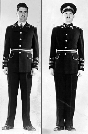
Possibly the most innovative proposals included these two examples. They differ primarily in the collar styling. Cuffs, shoulder straps and trousers would exhibit regimental colours.
The new uniform dress was being considered to replace full dress, undress and possibly mess dress, but its main purpose was to be for ceremonial occasions and walking-out. At the time, No. 1 dress uniform was in the early development stage and several distinctive types had been produced. The types most favoured were of midnight blue colour and manufactured of worsted serge or Barathea cloth. Additional samples had been manufactured in khaki and brown. The various prototypes which have been developed give consideration to the following characteristics:-

Similar in nearly all respects to the blue uniforms but manufactured in brown Barathea or serge.
HEADDRESS – The peaked service cap was to be of blue colour with a coloured regimental band. A blue beret was also examined. It was proposed the various headdresses as worn by Highland, Scottish and Irish Regiments would continue to be worn when applicable.

Three more propsaed uniforms. Many of these were simply variants on three basic themes – colour, collar and headdress.
JACKET –
(a) Collar – The decision as to whether an open collar or stand-up (patrol) collar would be adopted was undecided and a number of prototypes were produced. It was proposed that unit collar badges would be worn in either case. The use of coloured regimental piping on the collar edges was also considered.
(b) Shoulders straps – The prototypes continued the use shoulder straps and both ‘sewn-in’ and removable were considered with and without coloured regimental piping. It was proposed that unit shoulder titles could be worn in either case.
(c) Sleeves – The concept uniforms included the use of regimental buttons and coloured regimental piping on the cuffs with both plain and pointed cuffs proposed.
(d) Buttons – Metal regimental buttons were proposed on the various prototypes.
(e) Breast-pockets – Prototypes included the use of breast-pockets.
(f) Side Pockets – The use of side pockets with and without coloured regimental piping.
(g) Girdle and Belt – The use of a regimental girdle (commonly referred to as Stable belts) for wear on ceremonials and the cloth belt to match the jacket for wear when walking out was advanced.
(h) Pattern – For Highland and Scottish units it was intended that the jacket be modified for wear with kilts or trews.
TROUSERS – The use of coloured regimental stripes or piping in the trousers.
SHOES – It was proposed that either shoes or boots may be worn depending upon the occasion.
SAM BROWNE BELT – In the case of officers the Sam Browne belt could be worn with the jacket.

These two proposals more closely emulated civilian dress. A beret was optionally considered. In any event the final decision would see the elimination of firage caps for Other Ranks and it would be 10 years before these were returned.
In any event, the final choice was more traditional with the simple blue serge selected but with the use of a coloured beret in lieu of the pre-war coloured forage cap. Although a “No.1” uniform is referenced in the 1947 Dress Regualtions there is no description of it. In fact, this order of dress would not be formalised until publication of the 1953 Orders and Instructions for Dress of the Canadian Army. Ironically, where No.1 was intended to replace Full Dress and Mess Dress, both of these orders of Dress made their way back into the Canadian Army – either with official sanction such as for the Brigade of Canadian Guards’ Public Duties responsibilities, or privately funded by Regimental Associations.

The new No.1 Dress uniform worn at the 1953 Coronation of HM Queen Elizabeth II. Photo courtesy Bruce Graham
Did you enjoy this article? Please ‘rate’ it by clicking on the stars below
by Colin MacGregor Stevens
Flags, swallowtails, pennants and licence plates have long been shown on vehicles to identify the VIP in the vehicle to friendly service personnel. For the purpose of this article we will call the flags, swallowtails and pennants and their variations “flags,” even though technically only the rectangular type was properly called a flag. Most such flags were used by the military, but they were also used by members of the Royal Family, the Prime Minister, the Governor General, Lieutenant-Governors, members of the Defence Council etc.
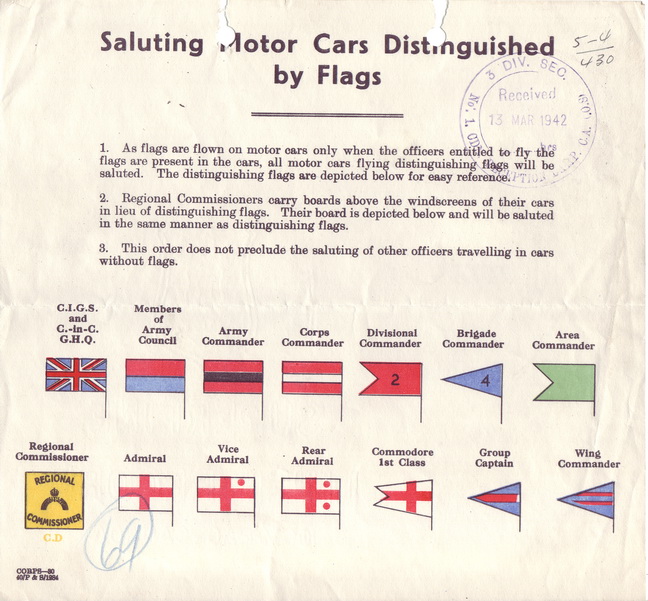
1943 dated circular explaining the British vehicle pennant system. The Canadian Army followed this regime, albeit with slight variations.
These flags were/are usually fitted near the front of the vehicle, either in the centre of the hood or on a fender. Field Marshall Alexander’s staff-car in the Canadian War Museum’s collection was fitted with two flag-staffs mounted in a “V” on the front centre of the hood. These flags have been called “Distinguishing Flags”, “Vehicle Distinguishing Flags”, “Flag, motorcar, distinguishing” and more recently “General Officers’ Flags and Pennants.” The RCAF called them “Pennants.” The standard RCAF design was a blue rectangular flag on which was a roundel which in turn had a maple leaf in the middle. In addition to this universal pennant there were pennants that identified the rank of the passenger. These consisted of horizontal red stripes denoting the officer’s rank. The Royal Navy, and thus probably the RCN, used flags in the form of a White Ensign with a symbol e.g. a solid red circle in the upper corner nearest the sleeve.
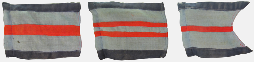
RCAF/RAF pennants denoting (left to right) Group Captain, Wing Commander, Squadron Leader. Courtesy Royal Westminster Regiment Museum
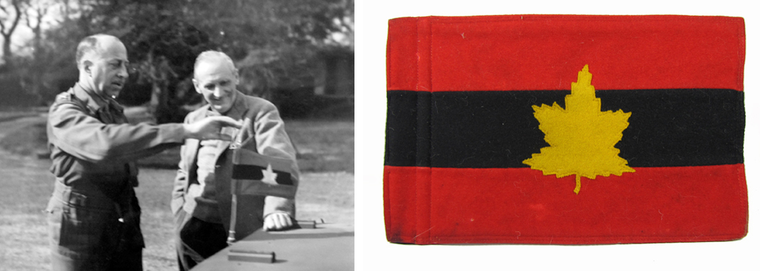
Vehicle pennant of the Commander of an Army, in this case Gen. Crerar GOCinC of the First Canadian Army who is showing it to Field Marshall B.L. Montgomery.
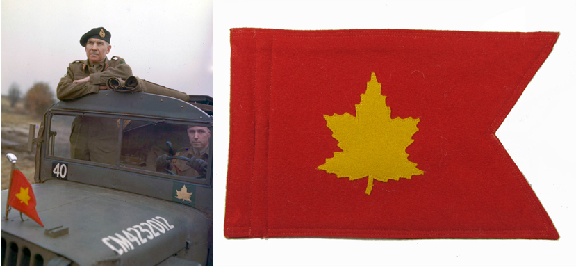
Pennant identifying a Divisional Commander, shown here used by Maj-Gen Worthington
The Canadian Army followed the British system during WWII, but after the war Canada followed Field Marshall Montgomery’s example by both flying a flag and showing a U.S. style Generals’ licence plate with stars on the front and rear of the vehicle. The plates were 6″ high by 12″ wide painted scarlet (later silver bordered red) and had the required number of holes along the centre for the bolting on of “General Officers’ Markings” (i.e. a chromed star or later a maple leaf symbol 2″ x 2″ with the arms 1/2″ wide). A Brigadier/Commander (Naval) would have a licence plate with one hole and thus could affix one star or maple leaf. A Major-General/Rear-Admiral was entitled to 2 symbols; a Lieutenant-General/Vice-Admiral 3; a General/Admiral 4 and a Field Marshall 5. At some point Canada replaced the stars on licence plates with maple leaves. When the vehicle was without the VIP passenger, the driver removed the flag and removed or covered the licence plate.

The US pattern general officer rank ‘star’ used by Brigadier Rockingham on his M8 Greyhound, in Korea.
ORDERS
It was necessary to inform the service personnel of the meanings of these flags, swallowtails and pennants. Canadian Military Headquarters published Technical and Training Bulletin No. 6 on 1944-08-20 and No. 8 on 1944-10-18. These bulletins identified the appointment of the VIP, a description of the device and the size (exclusive of the margin for the flag staff’s sleeve.) An example from T&T Bulletin No. 6 is the description of General Crerar’s flag: GOC – in – C, First Canadian Army Flag, motorcar, distinguishing Horizontal red-black-red strips of equal with gold Maple Leaf centrally placed on both sides. 9″ x 6″
Canadian Forces’ “Driver’s Regulations” usually have a section on driving VIPs. Drivers for the VIPs would have access to more than one flag in case of theft, loss, wear and tear or while traveling to other locations. It is believed that supplies of flags would be kept in relevant motor-pools for example. Such flags and their short flag staves were popular souvenirs and a smart driver would never leave them unattended and he or she would also have a spare tucked away.

Two styles of staves are shown here along with a Canadian Airborne Regiment pennant. (Author’s collection)
The flag staves were sometimes plain but in peacetime some eventually had a Maple Leaf with a bullet superimposed on top. The basic design was to have a screw-on knob on top which was wider than the sleeve. There was often a collar for the bottom of the flag to rest against, thus keeping it at the correct height above the vehicle. Flag staves had a quick release mounting system, usually with a bayonet mount or spring-loaded ball bearings on the sides and the base remained attached to the vehicle.
SHAPES
In the WWII Canadian Army system there were three basic types of distinguishing flags:
1. Rectangular flag for the General Officer Commanding a Corps, Army or Army Group.
2. A swallow-tail for the officer commanding a division.
3. A pennant for an officer commanding a brigade, usually a Brigadier.
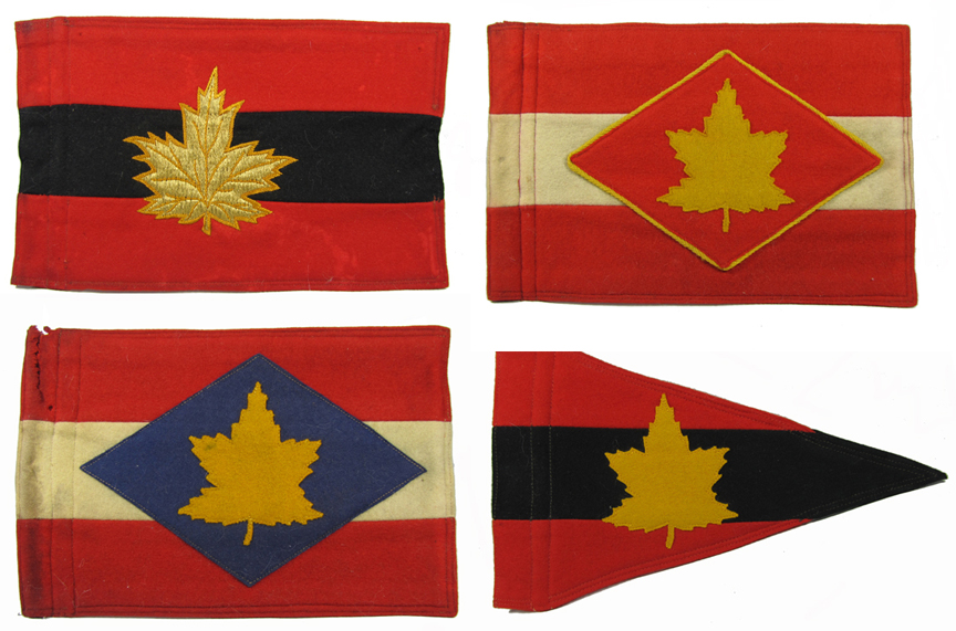
Top row, Army Commander, First Canadian Army. GOC 1 Canadian Corps.
Bottom row, GOC 2 Canadian Corps, Brigade Commander.

Pennant for Commander 27 Canadian Infantry Brigade in Germany, early 1950s. (Author’s collection)
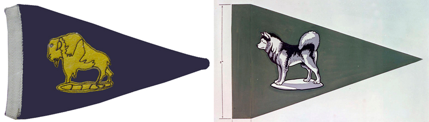
Left, Pennat flown by Brig Kay, GOC 19 Mil Group 1954 to 1958.
Right, Authorized vehicle pennant for the GOC, Alaska Highway System.
The designs of these “flags” continually evolves. After unification of the Canadian Forces and with a much smaller military than we had in WWII, NDHQ had apparently had more Generals, so other shapes were added.

Staff car for Major-General Stu MacDonald with the a swallowtail (borrowed from the author) and a two-maple leaf licence plate.
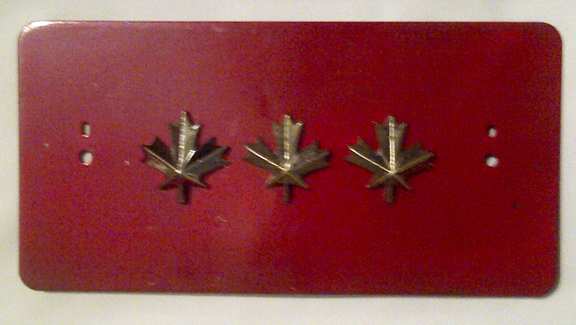
Canadian Forces vehicle licence plate. Issued in red for all General Officers although eligible RCAF and RCN could re-paint the plates in Air Force blue and Navy blue (respectively) at their own expense.
Post-war in Driver’s Regulations C-02-040-010/MB-001 Annex A Chapter 1 illustrates the Canadian Forces “flags” Except for the Prime Minister’s flag, a version of the Canada Flag, these all have a white background. All except the PM’s flag and the pennant have a small Canada Flag in the upper corner next to the sleeve. They are made of a synthetic material such as Nylon. One sees:
- Flags (rectangular) for the Prime Minister and Branch Head at NDHQ
- Swallowtail with straight top and bottom for Commanders of Commands, Northern Region
- Swallowtail with bottom angled up for Brigadier-General
- Pennant for Base and Unit Commanders

Vehicles pennants approved for use in the Canadian Forces, ca.1975

From the Canadian Airborne Regiment’s Standing Orders. The selection of pennants available to various officers of the Regiment.
The 1989 Regimental Standing Orders for the Canadian Airborne Regiment showed even more variations just for their unit. Each flag has a light blue upper half and maroon lower half, with a Canadian Airborne Regimental crest attached in the centre on each side.
MATERIAL
The WWII flags tended to be made of heavy wool with each colour sewn on separately. They were double sided flags so the construction was repeated on the other side (so that the image was not viewed in reverse) and then the two halves were sewn together. One does find staff car flags made of wool bunting, just like regular flags of the day, but these would not have stood up to much heavy use. The modern Canadian Forces staff-car flags are printed double-sided on white synthetic fabric and have a reinforced sleeve and edges.
IMAGES ON THE FLAGS
The basic colours and layout used by Canada in WWII were those in use by the British. For example all Divisional Commanders flew a red swallowtail. This was more or less fine for the First Canadian Infantry Division which had a red patch as their symbol, although it did not distinguish them from other British or Commonwealth divisional commanders. It would have been very unpopular with the other Canadian divisional commanders who used blue, French grey, green and maroon as their formation sign colours.

Note the use of the Division’s Garnet-coloured formation patch (with the addition of a gold maple leaf) by Maj-Gen Simmonds, GOC 5 Cdn Armoured Division, in Italy
Thus we see photos where generals have added their formation patch, sometimes in enlarged form, on each side of their red swallowtail. There was much customization, after all, it is only a higher ranking General who could tell them otherwise. For example the Royal Westminster Regiment Historical Society and Museum has on display Brigadier J. E. Sager’s pennant which has the wording “4 CDN INF BDE”. The museum has another of his pennants with a maple leaf in a circle and a letter “F” when he commanded “F” Group.

Brigadier J. E. Sager’s pennants. The top example was used when he commanded the 4th Canadian Infantry Brigade. This pennant has been adapted to a desk ornament and exhibits a locally-produced staff featuring the C/2 symbol of the 2nd Canadian Infantry Division. The lower pennant was used when he commanded “F” Reinforcement Group. Courtesy Royal Westminster Regiment Museum

Pennant to the Commanding Officer, “E” Reinforcement Group, in England, ca.1942.
NON-STAFF CAR FLAGS
One often sees fake staff car flags or other flags incorrectly identified as staff car flags. The key thing to look for is a “sleeve” for the flag staff to fit into. Most staff car flags are also quite heavy-duty as they were designed to take a beating with driving at speed. Most of the fakes have tie-strings or hooks at the top and bottom, but not a sleeve, and many are simply printed on both sides on a single layer of fabric. Size is an important determinant as they will usually fit within a 9″ x 6″ rectangle. The same image design was sometimes used in various sizes for camp flags, flags on board ships and station flags. There are also recognition flags flown by armoured vehicles.
Selected Bibliography
Canadian Army Overseas Technical and Training Bulletins No. 6 (1944-08-30) and No. 8 (1944-10-18)
Canadian Army Manual of Vehicle Markings May 1957
CAO 54-2 Vehicle Distinguishing Flags Annex A Issued 1959-03-23
Regimental Standing Orders for the Canadian Airborne Regiment (1989)
Driver’s Regulations C-02-040-010/MB-001 (post-1978)
by Clive M. Law
When, in 1937, the Department of National Defence (DND) went seeking a 15-hundredweight (15-cwt =3/4 ton) General Service truck, they had hoped to have both major Canadian automobile manufacturers work together in order to develop a common design. This hope was based on DND’s need to have a standardised vehicle available from domestic manufacturers to meet the Army’s needs in case of mobilisation.
As a result, General Motors Canada and Ford Canada set aside their natural competitiveness and worked closely together. Each delivered a pilot model in 1937that shared many parts. However, when DND asked each company to quote on 51 trucks (divided as 26 for Ford and 25 for GM), Ford, surprisingly, declined to bid and the entire contract was awarded to GM.

A soldier’s souvenir photo displays the 1940 Ford in a camouflage pattern. The door markings identify this as the Armoured Fighting Vehicle School at Camp Borden, Ontario. MilArt photo archives
This situation was not welcomed by DND who felt that Ford had not demonstrated an ability to produce, in any quantity, a military pattern vehicle that would be needed for a war which was almost certain. In order to bring Ford into the fold, DND justified a “sole-source” acquisition based on two factors; that the 1937-38 contract had been intended to be split between the two companies but this did not occur and, by awarding a similar sized contract to Ford for the 1939-40 contract, Ford would gain valuable experience and provide DND with two potential suppliers “for emergency production”. However, Ford was a reluctant partner.
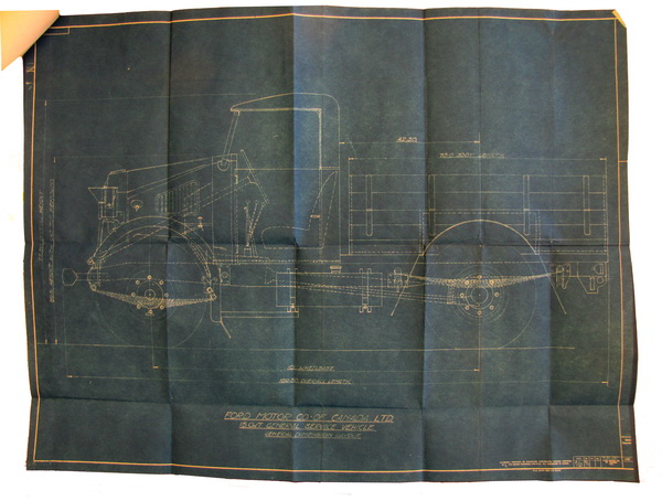
Drawings provided by Ford to DND to show the body and cab styles. MilArt photo archives
In late September 1938, following delivery of the GM trucks, DND wrote to Ford and asked that they provide a quote on a quantity of 15-cwt trucks. As the budget had not been finalized at this point, Ford was asked to submit prices for 20, 40, and 60 trucks. These were to be built to the British War Office specifications that had already been supplied to both GM and Ford prior to the 1938 contract. In keeping with DND’s strategic desire to build a national capacity for military vehicles, the letter stated that, while GM had supplied trucks equipped with tires from both the Dominion Rubber Company and the Firestone Tire & Rubber Company, Ford was to “arrange to bring into production at least one other company, and possibly two, depending on the number of vehicles finally ordered”.

One of the 50 Ford 15-cwt trucks contracted for in 1939 and delivered in early 1940. Photo courtesy Colin Stevens whose father, Lt. Stevens, is shown standing on the far right.
Ford remained surprisingly silent on this request to bid, and only replied after DND asked them again in February1939. Ford’s reply, signed by A.S. (Stan) Ellis, Ford Canada’s Service Manager, was both unexpected and unwelcome. Ellis, in a four-page letter, argued against building to the requested military specification, believing that a standard commercial truck should be acceptable to the Canadian Army. His arguments in favour of this included not just the cost but also the impact on Ford’s labour force, the effect on their commercial production, and the fact that Ford had recently supplied a large number of 244 15-cwt trucks to India, which differed from their standard model only by the provision of 9.00×18 tires which Ford obtained from their British affiliate, and special hubs to accommodate these. The truck proposed by Ford featured a 116-inch wheelbase and, intriguingly, a charge of $11.25 for “front fender alteration”. This is the first reference to the body style for which, by the end of the war, Canadian military trucks would be known world-wide.
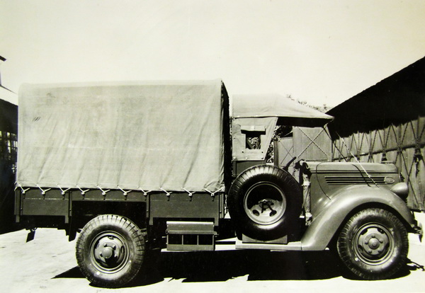
One of 244 Ford Commercial Pattern trucks supplied to India in 1939. MilArt photo archives
The question of body design had not previously been mentioned in Canadian contracts but, following a 1938 visit to Britain by Col. Carr, a suggestion was made to standardise on a common cab for Canadian military vehicles. The style identified at the time was that of the Quad Ant. The 51 trucks delivered that year from GM used a straight ‘box’ design and neither Ford nor GM had given any consideration to a common cab design.
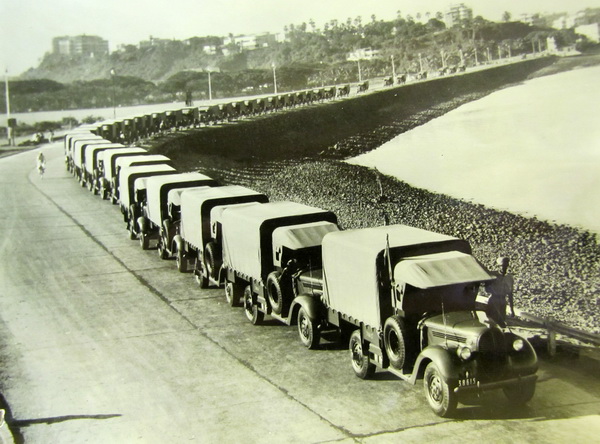
A line-up of the Indian contract 15-cwt trucks. Ford indicated to DND that they would prefer to produce commercial models instead of the military specification truck. MilArt photo archives
DND studied the Ford proposal and found that there was no advantage to accept the quote as presented. Although the truck would be useful for training purposes, this was equally true for trucks made by any of the other Canadian manufacturers. The analysis of the proposal showed that the wheelbase was 10 inches longer than the specification and this would affect the vehicle’s cross-country performance, the commercial-style cab limited aerial observation and did not allow a light machine gun to be mounted on the cab roof, the truck’s height would require the wheels to be removed in order to fit between the decks of a ship, and light armour could not be mounted to provide protection to the engine and radiator – all requirements of the specifications. But more importantly to DND, the purchase of these commercial vehicles would not accomplish the goal of providing Ford with experience in building a vehicle to military specifications.

A 1940-dated Ford photo showing the 15-cwt truck in ‘Knocked Down’ (KD) configuration. MilArt photo archives
The fate of Ford’s quote was sealed when the Chief of the General Staff wrote, “If Ford cannot supply them [military-specification trucks] … we should endeavour to get them elsewhere”.
Advised, by telegram, of DND’s position, Mr. M.H. Holden, Ford’s manager of fleet sales, visited Col. Carr in Ottawa, and promised that a new quote would be provided as soon as Ford could identify suitable suppliers. Carr reported this up the chain of command and suggested that “some credit should be given [to Ford]” and that it should be appreciated that the “motor industry in this country has very limited facilities for evolving design”.

Believed to be the same truck as shown above. Regrettably the door number is illegible. MilArt photo archives
Ford’s new quote was for a 101-inch, Cab-over-Engine (COE) chassis, complete with wheels, hubs, and tires. Absent from the quote was a cab or any sheet metal beyond the two gas tanks and body. Ford however, offered to supply blue-prints for the cab at no cost, which DND could then contract with another supplier. Ford argued that the cost of tooling for the production of such a small number of bodies was not financially feasible.
Once again, DND found itself with an unsatisfactory solution proposed by Ford. Within days of receiving the latest Ford proposal, Ellis and Carr met face-to-face. Carr made it very clear that DND sought to purchase a complete vehicle from Ford, which would allow DND to supervise a single contract and to avoid situations where different suppliers blamed other suppliers should a problem arise – such as the fit of the cab or body to the chassis. Chastened, Ford promised to co-operate with the Department and they promised to look into the possibility that the company itself would establish tools and dies for the production of the sheet metal components. Certainly Ford had some experience in providing a similar body as they had, in 1938, supplied a trial artillery tractor for the Canadian Army, built in cooperation with Britain’s Scammell Lorries Ltd.
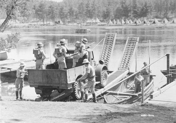
Canadian soldiers on a fording exercise. The Ford truck is identifiable by the tailgate and the headlamps. MilArt photo archives
In August 1939, with war just weeks away [comment – this is hindsight], Ford came back with another quote, which now included both a cab and a body, although Ford declined to supply a canvas top for the cab. Within weeks, Major G.P. Morrison, a staff officer in the Directorate of Mechanisation and Artillery, penned a memo to the Chief of the General Staff seeking approval to issue a contract to Ford for 50 vehicles. This memo is interesting, not so much for the history of the process or the justification for the purchase, but because it is the first documented use of the term “DND Pattern” when referring to the truck. This suggests that the Ford vehicle met most, but not all, of the British War Office specifications and basically sealed the Ford design as a Canadian specification, insofar as body, chassis, and running gear are concerned. By 1941, the term “DND Pattern” was officially changed to “Canadian Military Pattern” – the CMP.
Early in October, the Defence Purchasing Board issued a contract to the Ford Motor Company of Canada to supply 50 trucks, 15-hundredweight, at a unit price of $2,119.21. Although the original quote stated that the trucks would be painted “Dulux” 22, the contract was amended, by hand, to read “Khaki Green No. 3”.

Driver training at Camp Borden. Note the ‘L’ plate on the front bumper to indicate “Learner’
It would be early 1940 before the first of these trucks were delivered to the Canadian Army and, although additional orders were issued to both GM and Ford, these orders were for relatively small numbers. In fact, by the end of 1940, the Canadian Army could only boast 298 wheeled vehicles of all types under the Master-General of the Ordnance (MGO), and approximately 200 more under the control of the Royal Canadian Army Service Corps. Contracts for large numbers of vehicles would only be signed after the British Army left their Motor Transport in Dunquerque, and the Empire turned to Canada for the supply of military trucks in large quantities.
Archival sources used in the preparation of this article are to be found in Library and Archives Canada, Record Group 24, volumes 6293-6297, file block 72, dated 1930-1942.
by Clive M. Law
On 14 December 1935, the Chief Inspector of Armaments at the Woolwich Arsenal issued a formal invitation to interested parties to produce vehicles for military use to conform to various War Office (inexplicably abbreviated as WD) specifications. As a consequence, a copy arrived in the hands of Colonel N.O. Carr, (aka “no car”), Director of Mechanization and Artillery of the Canadian Army. Carr sailed to the UK to study the type of vehicles that were being built, especially those to WD specification, as the British intention was that vehicles would be standardised throughout the “British Commonwealth of Nations”.
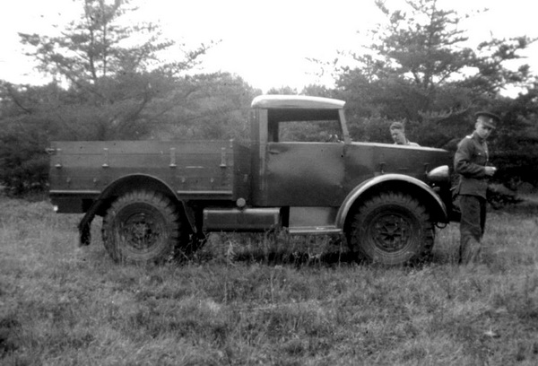
The 1938 Chevrolet 15cwt General Service pilot during trials held at Petawawa Camp. The truck is shown, pristine, in its new livery of ‘Dulux’ No, 22 paint. The trial was to ensure that the pilot met the specifications laid out by DND, including the ability to tow field artillery. August 1938. MilArt photo archives
At the time, the Canadian Permanent Force (PF) had only increased from 3,700 to 4,261 all ranks between July 1931 and July 1939, with all three PF infantry units under strength. Although, by 1936, the British had begun to convert its horse-drawn transport to motor vehicles, the Canadians could boast only a small number of Ford and Chevrolet light trucks of various types, as well as a few commercial pattern cars used as staff or reconnaissance cars.
An early experiment in mechanization occurred in 1934, when Ford of Canada and General Motors of Canada were each invited to build an experimental armoured car, to undergo testing by the Permanent Force. The deal involved the government paying for the materials and chassis while the companies paid for the design work and assembly. In the end the government paid $2,500.00 compared to Ford and GM of Canada who each invested $9,000.00 in labour and engineering to build their respective cars.

The trials at Petawawa Camp included use of the truck as a cable-layer. Just visible, behind the cab, is the top of the Mark II cable-layer. August 1938. MilArt photo archives
The Ford differed from the Chevrolet in that it had dual wheels on the second and third axles, a V-8 gasoline engine, and the armour plating was welded rather than riveted and bolted. Both armoured cars had a maximum speed of 30mph, and the Ford was able to do eight mph in reverse. It was intended that each vehicle would be armed with the Vickers Mk. VI medium machine gun, but these were delayed as the feed mechanisms were on the wrong side, having been originally designed by the British for right hand drive vehicles.
The cars underwent testing at Camp Petawawa, Ontario with the Royal Canadian Dragoons where both performed satisfactorily. The ten-wheel Ford performed best in off-road tests and the six-wheel Chevrolet excelled on roads. Orders for further cars failed to materialise because of budgetary limitations.

Truck number ‘Z38-1-10’ marked to ‘B’ Company, The Royal Canadian Regiment. It was found that, with the cab’s top removed and replaced with a canvas cover, the doors would bind. Orders followed that instructed that the doors were to be removed when operating with the canvas top. This order called for the DND markings to be moved from their usual location, on the door, to the body or elsewhere on the cab. The licence plate shows 1939. MilArt photo archives
In December 1936 the Canadian Department of National Defence (DND) hosted two conferences with Ford and GM to discuss short wheelbase vehicles.In the first meeting, the requirements of the Department of National Defence were outlined by Colonel Carr:
“It is the policy of the Department to employ motor vehicles of Canadian manufacture to the fullest possible extent. However, with a view to a possible future condition in which maintenance of the Canadian Forces by the War Office is necessary, it is imperative that conformity to W.D. Specifications be adhered to insofar as is possible.”
The decision reached at the conclusion of these meetings was that production in Canada of short wheelbase vehicles was to conform to WD Specifications, and to use a maximum of standard components. For the present, only the 15-hundredweight (15-cwt, or 3/4-ton), four-wheel,98-inch wheelbase was under consideration. DND stressed that their intent was that a military 15-cwt pilot model be developed by both Chevrolet and Ford, using the existing commercial chassis and that the two pilots be developed in parallel.
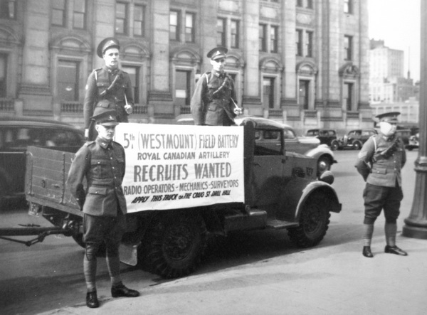
In 1933, 5th Field Battery was equipped with 18-pounder field guns which they retained up to early WW2. When mechanized the guns would have had pneumatic tires, as would the limbers, in lieu of wooden wheels. Sometime in 1939. MilArt photo archives
Just days later, General Motors of Canada General Manager H.J. Carmichael, and W.R. Campbell, President of Ford of Canada, met with Master-General of the Ordnance, Major-General Caldwell. Campbell and Carmichael agreed to co-operate with the DND in regard to the development of War Office pattern, short wheelbase vehicles, and agreed to pool resources to achieve this with minimum capital outlay. Both executives took the opportunity to remind DND that they had previously expended a significant amount of money in developing the armoured car, and it was hoped that DND was not seeking co-operation on the same financial basis. That said, Carmichael said they could provide a 98-in 4-wheel pilot model at cost, and Campbell said he might be willing to co-operate on the same basis. They also hoped that purchases of vehicles would be split equally between the companies.

The Canadian Armoured Fighting Vehicle School, at Camp Borden, Ontario, was the only Canadian home-based unit to apply a camouflage scheme to their vehicles, circa 1940. This example exhibits the full canvas cover provided for vehicles destined for general duties only, artillery tractors did not included these. MilArt photo archives
In February 1937, both automakers met and discussed possible modifications to Ford and Chevrolet standard commercial chassis to meet the WD specification. GM had already completed drawings showing proposed modifications to the Chevrolet chassis. Briefly, the GM proposal provided for moving the front axle assembly to the rear, moving the driving controls and steering gear forward, and moving the rear axle forward. These changes resulted in providing a wheelbase of 106 inches with a distance from the back of the driver’s seat to the centre of the back axle of 51½ inches. Specified loading space was thus provided to allow for fitting of standard WD pattern bodies.

The top halves of the body have been folded down on this example, also from the Canadian Armoured Fighting Vehicle School, circa 1940. MilArt photo archives
On the other hand, Ford had encountered difficulties and had made little progress with their design. Because of the transverse spring assembly on their front axle, it was impossible to move the axle to the rear as was proposed for the Chevrolet chassis. Moving the driving controls forward presented difficulties owing to the width of the engine. The rear axle, however, could be moved forward 19 inches, leaving a wheelbase of 112½ inches with the specified loading space behind the driver’s seat. Slight adjustment of the driving controls might allow a further shortening of three or four inches, although further adjustment would be possible only by altering the front springs to the semi-elliptic type. The Ford pilot was built in a new 50 x 100 feet bay, dubbed the “Pilot Bay” which Ford had set up in the basement of its Windsor plant.
On 30 March, DND clarified the following specifications for Ford:
- A wheelbase of 108½ inches, together with Ford’s proposed arrangement of controls, seat, front fender, and engine and hood were acceptable.
- A collapsible canvas hood was required.
- Monroe shock absorbers would be accepted for trial.
- Front wheels were not to be fitted with chain lugs.
- Ford would supply a load-carrying body with the pilot model truck in accordance with drawings and specifications.
- A full-width, fixed windscreen without provision for opening would be acceptable. The glass could be in one or two sections.
The next day DND confirmed the following with GM:
- The width of the rear track should be as close to that of the front as possible and therefore delaying delivery of the special 14-in. brake drums until 17 May was acceptable as it would enable a 62-inch rear track.
- Attachment of Lovejoy shock absorbers was acceptable.
- No spare tyre was to be carried.
- DND would send drawings and specifications of a load-carrying body, and Oshawa would supply the body for the pilot truck.
- A fixed top of sheet steel and tubular frame construction was acceptable, provided it was satisfactory and inexpensive; otherwise a collapsible canvas top would be used. The steel top should be able to withstand the stresses of cross-country travel.
- A full-width fixed windscreen without provision for opening was acceptable, in either one or two sections.
- If the fixed top and windscreen could be detached from the chassis to reduce overall height when shipping, then this would be an advantage, if it did not unduly complicate the design.
Ford suggested that the bodies for the two pilot models should be made by the same source in view of the desired standardisation of bodies. Ford had been asked to withhold ordering their body until they received the drawings from Ottawa and further instructions.

These trucks are plated in British Columbia and are dated 1940. The trucks are believed to be transporting soldiers of the Westminster Regiment. Photo courtesy Colin Stevens.
The body’s design specifications, as supplied to both GM and Ford, stated that the woodwork was to be of seasoned ash and white oak, free from knots, saps, shakes, wavy edges and defects. Metal parts were specified to be of high quality forged steel and all bolts and nuts were to be of steel. The body was to have hinged sides and tailboards. Sides and tailboards were to be of 1-inch planed white ash, tongued and grooved where applicable and finished with a “V” joint outside. The floor was to be of 1¼-inch planed white oak with plain butt joints. The spacing of the longitudinal runners on the body was not specified, but was to be in accordance with the width of the chassis frame for which the body was intended. The assembled body was to be painted throughout in Service Green No.22 “Dulux” including the interior, under-surfaces, and hardware. A plate with the name of the manufacturer, date of completion, and reference number was to be engraved or stamped on it, and attached to the left lower corner of the body. This body description was in keeping with the British III/1 body specification
The body manufacturer chosen was Canada Carriage & Body Company Limited, of Brantford, Ontario, who informed DND that ash was very difficult to obtain in Canada and that which was obtainable was of non-uniform quality. As an alternative, they suggested oak and this recommendation was accepted by DND. While the body was being built, it became clear that GM would have to request changes in the specifications in order to fit their chassis. A 36-inch outside width of the main sills was required to suit the Chevrolet chassis frame, and a 75¼-inch outside width to suit the overall width of the tyres.
By the end of May 1937, neither pilot model had been completed. There were, in fact, outstanding design problems to be sorted out. DND inspected the GM pilot truck on 16 June 1937. The major components, with the exception of the front hub assemblies and the body, were complete and partially assembled. The front hubs and body were expected to be available that week. There still remained considerable work on minor details and fittings, which was estimated to take another two weeks. Delivery was expected therefore about 10 July. The truck appeared to be well designed and constructed. Minor criticisms were made and rectification was promised. These points included connections to front shock absorbers, spacing of foot controls, battery box, and the rear window in the cab.

Two trucks belonging to the Princess Patricia’s Canadian Light Infantry, at Camp Dundurn, Saskatchewan. Surviving records show that this regiment received four Chevrolet 15cwt GS trucks in 1938. Photo courtesy Princess Patricia’s Canadian Light Infantry Museum and Archives
Both pilots were finally ready in August. At the request of DND they were commercially licenced and the manufacturers were asked to drive them from the respective plants to Ottawa. The GM truck was delivered and viewed by the Chief of the General Staff and then driven by a Staff Officer to Camp Petawawa for acceptance trials. The Ford was delayed and permission was given for this vehicle to be driven directly to Petawawa.
Once delivered, the trucks were given DND numbers 37-1-1 for the Ford and 37-1-2 for the GM. Instructions issued by DND later required that vehicle numbers be painted on the doors, although this was not always followed.
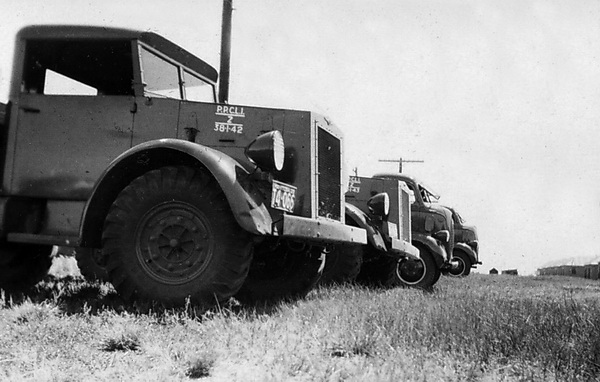
This photo clearly shows the approved vehicle marking policy which called for the unit abbreviation, the letter ‘Z’ denoting ‘Truck’, the year of purchase (1938), a separator to denote that the truck is the responsibility of the Ordnance (1) and the consecutive number of the truck within that year (42). Photo courtesy Princess Patricia’s Canadian Light Infantry Museum and Archives
During the trials, each truck accumulated approximately 1,000 miles of road and cross-country driving. Considering that the two trucks were, in effect, new models and had been put together in a matter of seven months, the faults identified by DND tended to be relatively minor. The Ford’s weak point was its steering, which had too much play, while the GM vehicle suffered from weak springs. There were no recorded damages, breakages, or involuntary stops during the trials.
DND concluded that the vehicles were generally satisfactory in respect of design, performance, and ability to stand rough usage. However, certain minor modifications were required for subsequent production. It was considered that the designs of both the Chevrolet and Ford 15-cwt trucks would be stable, and that a firm specification to govern future supply would be completed by 1 October 1937.
In accordance with regulations, the doors have been removed while operating the truck with the canvas top. The vehicle marking shows that it belongs to ‘A’ Squadron of the Royal Canadian Dragoons and is being used as a wireless (signals) vehicle. Courtesy Royal Canadian Dragoons Museum and Archives
DND intended to order 70 of the 15-cwt trucks that financial year. This quantity would meet provisional establishments of the Permanent Force. A list was compiled of all existing 15-cwt trucks, or equivalents, which were to be replaced by new trucks, traded-in, or retained for instructional purposes. The oldest was a 1928 Durant Coach. The DND fleet also included a 1929 Chevrolet LQ stake truck, a 1934 Chevrolet light delivery van, two Chevrolet pickups, and a 1½-ton stake truck, all 1934 Models. There were eight Crossley Staff Cars to be sent to schools. All others were Ford 1931 to 1936 Model 2-ton stake trucks, station wagons or Phaetons. Ten 1936 Ford 2-ton trucks were to be retained, to be supplemented by the new 15-cwt trucks. It was estimated that 36 new GM and 36 Ford trucks were required. This represented 35 new trucks from each firm plus the two pilots.
Rear view showing body detail. Based on a British pre-war specification it is almost identical to the standard, wood, General Service body used on Canadian Military Pattern trucks throughout the Second World War. Courtesy Royal Canadian Dragoons Museum and Archives
In a cash-strapped government weathering the Great Depression, DND was told that the quantity was excessive and to re-assess its needs. In accordance with government direction, the Permanent Force requirements were revised and a quantity of 51 new production trucks was put forward for approval as the bare minimum.
On 14 January 1938, the Director of Contracts at DND formally wrote to Ford Canada and GM of Canada requesting quotations from each of them for 15-cwt trucks. Of these, Ford was to quote for 25 trucks and GM for 26. Surprisingly, Ford officially declined the invitation to bid, as they were not able to produce them to the required price.However, given Ford’s need to use a modified 101-inch forward-control chassis, which was not even going to start production until the early spring of 1938, and because even then the front axle to be used could not cope with the requisite 16-inch wheels, it was arguably impossible for Ford of Canada to have tendered in any event, unless DND was prepared to pay the considerable costs of tooling-up for special 14-inch brake drums.

The old and the new meet during a pre-war exercise. Note the jury-rigged antenna. Courtesy Royal Canadian Dragoons Museum and Archives
With no other option, DND invited GM of Canada to tender for the supply of all 51 vehicles. In practice, the trucks were ordered in two linked contracts, the first for 35 trucks, at a price of C$102,590.47 and a further order for 16 trucks at a price of C$46,158.81, to include a 10% fixed profit in each case.
Trucks destined for simple cargo duties were to be equipped with a canvas cover, while this was dispensed with for trucks that were to act as tractors for anti-tank artillery. Existing trucks that were not traded-in, or that continued to be used, were limited to instructional purposes only, and were not to be driven. This was intended to train the units concerned in mechanisation.
In keeping with DND practice, each truck was allotted a DND number, starting with 38-1-2 and continuing to 38-1-52. The numbering used at the time consisted of the year of contract (1938), followed by the single digit (1, which doesn’t appear to have any relevance as every DND vehicle shares this same number), and then the sequential number of the vehicle obtained under the contract. In late 1939, following British Army practice, the DND number (also termed the “census” number) was prefixed with the letter “Z”, i.e. Z38-1-46. The factory serial numbers were 815312801 to 815312835 for the first purchase and 815314928 to 815314943 for the second. The GM numbering system can be read as the model year (8), followed by the model number (1531), and then the sequential production number for the model.

PPCLI on exercise at Camp Shilo, 1939. Courtesy PPCLI Museum and Archives
Even though Ford declined to bid on the contract, the process proved that two competing industrial giants could set aside their corporate differences in order to work together in the national interest. The development and subsequent purchase of these 15cwt General Service trucks provided a solid basis for cooperation and interchangeability of parts and assemblies between GM and Ford. Thanks to this foundation, Canada was well placed to assume a significant role during the Second World War as a major supplier of wheeled military vehicles – known around the world as the Canadian Military Pattern.
Part 2 will address the Ford 15cwt contract
Archival sources used in the preparation of this article are to be found in Library and Archives Canada, Record Group 24, volumes 6293-6297, file block 72, dated 1930-1942.
The author wishes to acknowledge the work undertaken by the late David Hayward whose unpublished work was often consulted in the preparation of this article.
by Clive M. Law
Shortly after Canadian Confederation, in 1867, the No. 2 Troop and the Royal Guides Troop of the Montreal Cavalry Squadron were disbanded. This left No. 1 Troop as the sole militia cavalry unit in Montreal.
In 1877, the Dominion government consolidated the remaining Quebec independent troops positioned along the U.S. border into two Cavalry regiments. The first of these was the 5th Dragoons (5th Provisional Regiment of Cavalry) which was the first cavalry regiment in Quebec. In 1879, the second regiment, the 6th Regiment of Cavalry (Hussars), was formed. This regiment incorporated the above-noted No.1 Troop.
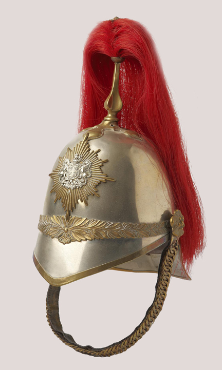
The helmet, circa 1880, is of white metal construction. Across the front seam a decorative gilt band of olive leaves and a band of oak leaves conceals the rear seam. A plain gilt chain backed with leather and attached to the helmet with gilt rosettes. The plume is attached to the helmet through a gilt spike resting on a plain quatrefoil. Author’s collection
The 6th, as a Hussars regiment, adopted the uniform of the British 13th Hussars, a regiment which had seen service in Canada between1867-1869 and whose dress had become the de facto Hussars uniform in Canada.1 The 6th Canadian Cavalry Regiment (Hussars) wore a tunic of blue, single breasted and fastened with six gold olivets. On each side of the chest were six loops of gold chain lace with caps and drops. The facings were buff.2 Strangely, this new regiment chose to wear the plumed cavalry helmet, more usually associated with British yeomanry regiments, in lieu of the Hussars Busby. The helmet, of white metal construction rather than of the more typical brass, features a plain pattern, eight-pointed, diamond-cut, gilt star upon which is mounted a silver General List badge (this badge is the British coat of arms and is normally worn only by unattached officers). The plume is horsehair dyed red.

The details of the uniform can be clearly seen in this print by Henry Richard S. Bunnett (1845-1910), a British artist who resided in Canada from 1885 to 1889.
The 6th Canadian Cavalry Regiment (Hussars) is perpetuated, through the No.1 Troop, by the Montreal-based 17th Duke of York’s Royal Canadian Hussars, a unit of the Canadian Forces Reserves.
1. Chartrand, Rene, Canadian Military Heritage, Vol. II, 1995, Art Global, Montreal. Published under the auspices of the Department of National Defence, (Directorate of History & Heritage)
2. Regulations for the Dress of the Officers of the Army, Horse Guards, War Office, 17 May, 1883.
by James J Boulton
The writer’s interest in the Regiment of Canadian Guards began with a peripheral interest in regimental traditions. In 1953, this regiment was drawn from seven Canadian infantry regiments as well as battalions from the Governor General’s Foot Guard and the Canadian Grenadier Guards. It thus absorbed the histories and honours of its component regiments, and adopted the uniforms and traditions of existing guards regiments.

Sergeants-Major of the Canadian Guards Depot and of each of the first three battalions
The blue forage cap is of particular interest. That for uncommissioned ranks of the British and Canadian foot guards regiments differed from those of other military units in its distinctive style, the use of rank distinctions in the badge and peak trim and its more important role and wider use in the Orders of Dress than the No.1 Dress Cap for other regiments. Officers’ caps differed from other regiments and corps in that there were no rank distinctions.
OTHER RANKS’ FORAGE CAP

Other Ranks Forage Cap
The specifications[1] called for the cap to be the crown and peak military type with chinstrap, scarlet headband and scarlet piping around the crown, the pattern of the British Grenadier Guards[2]. The “guardsman” style called for a more vertical peak, producing a commanding appearance. The Canadian Guards’ regulations specified that the original shape of the cap was not to be altered, implying that the peak was not to be “set up”, or made more vertical.
Peak construction
No nation has a more comprehensive system of rank designation on the cap than France, where every rank could be read from the cap. Most British and Canadian Foot Guards’ ranks below commissioned officer could be read from the cap peak.
The specifications called for the peak to be two and one quarter inches deep at the centre and constructed in three plies. Top ply was black plasticized vinyl chloride, slightly thicker for peaks featuring soutache trim. An inner was ply fibre or pulp board, and the bottom ply “hatters green” diced plate leather.
The peaks with brass rank stripes were finished with yellow brass to form a binding 1/4 inch in width on the top and undersurface of the peak. The binding for peaks with soutache rank stripes was black plastic stitched to produce a bound edge 3/16 inch in width.
Brass rank stripes were 1/8 inch wide, shaped to the contour of the front edge of the peak, each with three soldered copper pins 1/2 inch in length on the underside. The pins were passed through the top two plies of the peak and clinched before the application of the bottom ply. The first stripe was to be 3/16 inch behind the metal binding and each subsequent stripe 3/16 inch apart. Alternately, the pins could be passed through all three plies and an extra piece of “hatters green” leather applied to the underside of the peak immediately behind the inner edge of the binding.

Sergeant’s Forage Cap
Soutache (Russia) braid was a doubled cord, resembling an electrical wire, made of good quality gold, 1/8 or 3/16 (for band personnel) inch in width, stitched to the upper ply of the peak, the first row placed 1/4 inch above the unfinished front edge and the other rows immediately behind the first row.
The ranks could be distinguished as:
Lance Corporal and Guardsman – brass binding
Lance Sergeant and Corporal – brass binding, one brass strip
Sergeant and Colour Sergeant – brass binding, two brass strips
Staff Sergeant – three rows soutache braid
Warrant Officer, Class II – four rows of soutache braid
Warrant Officer, Class I – five rows of soutache braid

Regimental Sergeant-Major CJ Scott
Bandsmen
It is a common practice for the headwear for regimental bands under British influence to differ from the regimental pattern in some way.
Drum Major – brass binding, two brass strips (as for Sergeants)
Band Warrant Officers and Staff Sergeants – three rows of 3/16 inch soutache braid
Musicians up to, and including Band Sergeants – one row of 3/16 inch soutache braid

Canadian Guards Colour-Sergeant
BADGE RANK DISTINCTIONS
The regulations called for the cap badge to be mounted centred on the cap so that to top of the cap band bisected the star, but in practice, this varied. Certain rank distinctions within the uncommissioned ranks were also made by the cap badge.
The badge was 2 inches high for all ranks. The ten-pointed star was brass, white metal or silver. The annulus containing the regimental motto and three maple leaves was brass or gilt.

Rank distinctions of the Canadian Guards cap badge.
Warrant Officer Class I – silver, gilt and red enamel (the officers’ pattern)
Warrant Officer Class II and senior non-commissioned officers – white metal, brass and red enamel
Lance Sergeant and below – brass and red enamel
ORDERS OF DRESS (BELOW COMMISSIONED RANK)
The Guards’ coloured forage cap was worn in a full range of Orders of Dress[3], in marked contrast to other military units.
Full Dress – State occasions, public duties and guards of honour (blue cap as an interim headwear when not in view of the public)
Patrol Dress – W.O. I and Drill Sergeants, State functions when Full Dress not ordered; church parades; funerals; courts martial; guards of honour; as ordered.
Patrol Dress – all ranks, Walking out, informal and social occasions
Mess Dress – Warrant Officers and senior non-commissioned officers, Social functions in the Sergeants’ Mess or where deemed appropriate
Service Dress – W.O. I, Unit parades and walking out
Summer Service Dress – all ranks, Unit parades and walking out
Battle Dress – all ranks, (blue cap in garrison only), unit parades, garrison dress, walking out
Summer Field Dress – all ranks, (blue cap as ordered), summer garrison and training dress.
Shirt sleeve order – all ranks, (blue cap as ordered), summer garrison and higher Headquarters buildings.
Drill Sergeants were to wear the blue forage cap at all times in barracks and when walking out in uniform.
In summary, the cap was generally worn by all uncommissioned ranks except in field, training, combat and fatigue duties. The use of dress headwear with khaki uniforms in Britain dates at least to the Belfast riots of 1907, when an infantry regiment was ordered to wear their 1878 pattern dress helmets in a small hope that they would offer more protection [4]
OFFICERS’ FORAGE CAP
The officers’ forage cap was specified to be the distinctive Coldstream Guards pattern[5]. This was midnight blue cloth with a 1-1/2 inch black mohair band. The peak was finished with 1-1/4 inch wide gold wire bar embroidery.
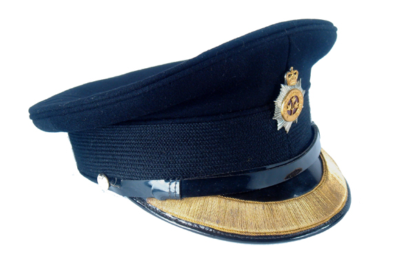
Pattern of Forage Cap common to all Guards Officers.
Contrasted to other military regiments and corps, there was no distinction between company and field grade officers, all wearing the same cap peak.
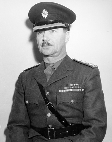
Canadian Guards Officer in Service Dress
The regulation gilt and silver forage cap badge was worn, while a small version, 1-1/4 inches high, was worn on the khaki Service Dress cap, again a Coldstream Guards tradition.
Orders of Dress
The blue forage cap was to be worn with all six versions of Patrol Dress, both with blue and white uniforms, Mess Dress and Service Dress for unit parades and garrison duties.
1 Specification CLO-2-4-25C
2 A Comprehensive Literary and Photographic Record of Full Dress Clothing Inspectorate of Clothing, Ministry of Supply August 1955
3 The Canadian Guards Regimental Standing Orders 1966
4 Harris, R.G. Mixed Dress 1906-1964 Military Historical Society Bulletin XXI (84) May 1971
5 The Canadian Guards Regimental Standing Orders 1966
This article first appeared in Military Collectors’ Club of Canada Journal, volume 242, Fall 2010.
