
by Roger V. Lucy
In North-West Europe in November 1944, the 18th Armoured Car Regiment (12th Manitoba Dragoons) was seeking a means to deliver more high-explosive firepower, than could be provided by their Staghound armoured cars’ 37mm guns. The Dragoons were often too far out ahead to call in artillery support, but needed an “on-call” HE capability to soften up resistance. This was supposed to be supplied by the Staghound III, with a 75mm gun, but it had yet to enter production, Efforts to obtain some M7 Priest 105mm self-propelled guns were also unsuccessful. With the permission of HQ First Canadian Army, the Manitoba Dragoons borrowed four obsolete Rocket Launcher Rails Mk.I and a number of 60 lb. warhead aircraft rockets, used with the Hawker Typhoon from the RCAF.
The modifications were a carried out on 19 November, 1944, by 40 LAD. The rails were attached to the mantlet so the rockets could be elevated with the gun (no doubt with some difficulty, given the rig’s extra 200 or so extra kilos). Rotating the turret provided the traverse. The edges of the rails protruded about 3 inches (7.5 cm) beyond the sides of the armoured car.
![Photographs from First Canadian Army’s Weapons Technical Staff Officer Major Sangster’s report showing the rails fitted to a XII Manitoba Dragoons Staghound.The vehicle bares the tac sign of the HQ Company]](https://milart.blog/wp-content/uploads/2014/09/xii-dragoons-staghound-rl-11-44a1.jpg)
Photographs from First Canadian Army’s Weapons Technical Staff Officer Major Sangster’s report showing the rails fitted to a XII Manitoba Dragoons Staghound.The vehicle bares the tac sign of the HQ Company]

The system was tested on 20 November and more formal trials were held at St. Phillip’s Island – under the supervision of First Canadian Army AFV staff – on 26 November and 2 December. Results were generally promising, although – due to limitations of the ground – the ranges achieved could not be accurately measured. It was estimated that rockets went anywhere from 100 to 3,000 yards (90 to 2,750 metres). Accuracy (particularly in terms of range) was wanting, and at short ranges the rocket warheads often failed to detonate. Neither the car nor its crew suffered as a result of the rockets’ back-blast and the trials were considered sufficiently successful for First Canadian Army to recommend to CMHQ that further development be undertaken.

The rocket Staghound being readied for its test firing in early December 1944. MilArt photo archives
In the meantime 12th Manitoba Dragoons continued to work their original design. In February 1945, 40 LAD was preparing to fit rocket rails to other Staghounds to support patrols across the Waal river, but this was cancelled when the regiment was ordered into a mobile offensive role.
After the 12th Manitoba Dragoons CO, Lt-Colonel Roberts, was given command of 8 Canadian Infantry Brigade, he considered mounting rockets on the sides of a Universal Carrier, but nothing seems to have come of this. However, another formation, 4th Canadian Armoured Brigade conducted a similar experiment, fitting two pairs Typhoon launcher rails to the sides of one of their half-tracks. The rails were pivoted to allow range adjustment and a sheet metal guard was fitted over the top of the vehicle to protect the crew from the rockets’ back-blast. Ranges of up to 1,500 yards (1,350 metres) were attained, but accuracy was erratic. First Canadian Army’s Weapons Technical Staff Officer Major A.G. Sangster, concluded that, given the ballistic unsuitability of these rockets for a ground role, it had “worked as well as expected.” Sangster believed the idea seemed to have potential and he recommended the development of a prototype more suited to a ground role. In essence, this was same conclusion reached following the Staghound trials, but in this case there was no follow-up to Canada’s own “Stuka (or rather Typhoon) zu Fuß (21cm rockets mounted on the sides of the SdKfz.251 half-track).”

Photographs of 4 CAB’s half-track mounted rocket launcher from First Canadian Army’s Weapons Technical Staff Officer Major A.G. Sangster.s report.
The British Coldstream Guards also undertook similar experiments in early 1945 fitting Typhoon rocket launcher rails to the sides of a Sherman Firefly. Christened the Tulip, it reportedly had the good luck to hit, and kill, a Tiger.
While this ended field expedient rocket launchers Canadian Military Headquarters (CMHQ) in London took up the proposal, and in January 1945 conducted their own tests, using a similar arrangement. While the results were promising, the performance of the Mk.I rails was deemed unsatisfactory. British experts pointed out that air-launched rockets were unsuitable for ground use, and recommended that further development focus on SEAC spiral launchers, using 3-inch (76mm) and 5-inch (125mm) rockets – types already allocated to First Canadian Army for the Land Mattress. The War Office saw no requirement for rocket-armed armoured cars, but was interested in developing cast aluminum spiral launchers that could be mounted on any armoured vehicle. Staff at CMHQ, took the idea further, drawing up a concept for a dedicated vehicle, with the turret replaced by the launcher tubes and an observation cupola for the operator. Work was therefore continued, as a long-term development, still using the Staghound as the platform.
With help from British rocket experts at CEAD, a launcher using six cast aluminum spiral launching rails was developed. CMHQ ordered 12 pilot cast-aluminum spiral launcher tubes from a Birmingham foundry – the Northern Aluminium Co. The results were unsatisfactory, only five tubes were delivered before the rest of the order was cancelled in July. In order to proceed with the trials, No.1 Canadian Base Workshops (1 CBW) fabricated a set of eight steel tubes. After looking at two possible mounting options 1 CBW mounted four on each side, in banks of two, attached to the turret by angle irons and steel tubing. The rails were linked (with a counter-weight) to the gun barrel, and elevated with it. A range dial (in the form of a quadrant, attached to the gun’s trunnions) allowed more refined aiming.

This photograph from the report on the trials of the Staghound Rocket launcher at Ynys-Las South Wales, in April 1945 shows details of the mechanical linkages of the Rocket Projector mounting.

This photograph provides a front view of the rocket projector and mounting.

Here are further details of the mechanical linkages of the Rocket Projector mounting.

This photograph shows damage to the fender caused by the back blast of a rocket salvo.

Another view of the blast damage. The junction boxes for the electrical firing gear can be seen on the rear of the projector.
The revised system was ready on 5 April and tested on 26 April at Ynys-Las South Wales. Some 35 rockets were fired in all, with generally satisfactory results. While little harm was done to the crew, the back-blast of a full salvo damaged the rear mud-guards and activated the CO2 fire-extinguishers. In addition, ripple firing caused serious erosion to the launcher rails, eventually damaging one so much that the fin of one of the rockets was pulled off, causing it to break up in flight. The addition of blast deflectors to protect the CO2 release handles was recommended.

This series of photographs taken at Ynys-Las on 26 April 1945, shows the Staghound rocket launcher undertaking a shoot. The vehicle belongs to 1 CACRU. Note the damage to the fender from the blast. This photograph shows the intensity of the back-blast.

Firing another salvo.

The Staghound fires a single inert round.

Reloaded, note the damage the back-blast has caused to the rear mudguard.
A new contract for cast aluminum tubes was awarded to High Duty Alloys Ltd. of Slough which was able to deliver. Getting range access delayed testing the redesigned launcher. It finally took place the British Chemical Warfare Establishment at Porton Down, in December 1945. The results were very successful; damage to the fins was avoided by champfering their edges. However – and not surprisingly, given Porton Down’s purpose – British interest in the system now concentrated on its potential for delivering chemical and smoke rounds. Work did continue of the project – to develop a suitable smoke round – at least into March 1946. Eventually the Staghound Rocket Launcher was returned to Canada.
Sources
Lucy, R,V., Secret Weapons of the Canadian Army, Service Publications, Ottawa, 2006
Library and Archives Canada RG 24 Series C‑3
Volume 9365, File 38/ARM VEH/32, T17 E1 armoured car
Volume 9376: 38/SD TECH RPTS
Volume 9378, file 38/WAR DIARY/1 WD DDEM [Directorate of Design, Equipment and Mechanization
Volume 9391 excised photographs for 55 series files
Volume 16288 WD No. 40 Light Aid Detachment, Corps of Royal Canadian Electrical and Mechanical Engineers (attached to 18th Canadian Armoured Car Regiment (12th Manitoba Dragoons),
Reel C-5777, file 55/553/1/ AFV(W) First CA correspondence
Reel C-5779, file 55/733/T85
C-8279 Army – Reports from 21st Army Group – Armoured Fighting Vehicles
Reel T-12714 WD 18th Armoured Car Regiment (12th Manitoba Dragoons) 1943/11-1945/01
You can rate this article by clicking on the stars below
For more information on the Stag rocket Launcher order “Secret Weapons of the Canadian Army” from Service Publications
by Mark W. Tonner
Introduction
After the Dieppe raid on 19 August 1942, and as a result of the high number of casualties suffered by members of Royal Canadian Engineers during the raid, a number of devices were devised whereby explosives could be carried up to sea walls and other fortifications, placed in position and detonated from a distance. All these devices involved some type of framework on the front of a Churchill tank,1 which was used to hold the explosives. As part of their development, on 18 February 1943, a composite Troop of six Churchill tanks of the 14th Canadian Army Tank Regiment (The Calgary Regiment (Tank)),2 Canadian Armoured Corps (hereafter referred to as the Calgary Regiment), commanded by Lieutenant V.J. St. Martin, were sent to Witley, Surrey, for special training exercises in connection with anti-tank mines and methods of clearing minefields and tank obstacles. They were used in the trials of two of these experimental explosive devices, under the auspices of the Special Device Branch of the British Department of Tank Design.

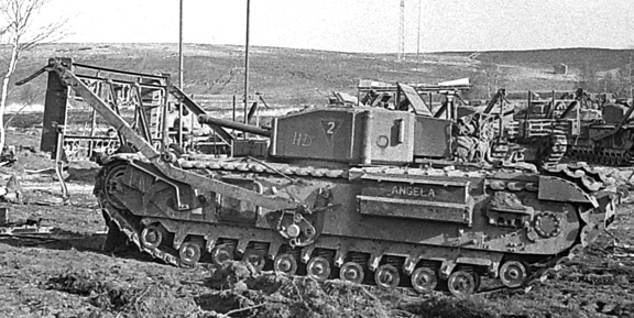
A front view a Churchill Mark III tank, named ANGELA, of No. 2 Troop, “A” Squadron, The
Calgary Regiment, at Whitley, Surrey, fitted with the “Onion” explosive device. Note the pair
of hinged legs at the bottom and two fixed outward-facing legs at the top. Also, of note, is
the placement of the high explosive charges on the sides and face of the framework. Source:
authors’ collection.

A right-side view of ANGELA, showing the right-side arm, attached to a bracket which supported the vertical “Onion” explosive device framework on the tank’s front. Note also, the two outward facing legs, attached to either corner of the top of the framework. Source: authors’ collection.
The “Onion” explosive device
The “Onion” was an explosive device designed to allow a Churchill tank to move explosive charges into place to breach or demolish obstacles. Arms attached to brackets on the sides of the tank supported a vertical framework with a pair of hinged legs at the bottom and two fixed outward-facing legs at the top. Six oblong 30-pound (14-kilograms) high explosive (HE) charges were attached, three to a side, to the outer face of the framework in boxes, or in a pattern on the outer face of the frame work, to suit the intended target. The frame was then driven into place and released, with the two hinged legs on the bottom of the frame meeting the ground first, forcing the frame to fall forward against the obstacle, while the tank reversed away, approximately 100-feet (30-metres), and trailing an electric ignition cable. Once the tank had reversed away a safe distance, the charges arranged on the framework were detonated. The frame could also be hung from obstacles, such as walls or bunkers, by using the two outward facing legs on either corner of the top of the framework.
The “Onion” worked well against obstacles such as “Dragon’s Teeth” (concrete tank traps) and steel beach obstacles, but was not always effective against walls or bunkers, because the frame did not always position itself correctly after being released, reducing the impact of the explosion. The “Onion” was deemed a failure and never entered production.
A left-side view of ANGELA, of No. 2 Troop, “A” Squadron, The Calgary Regiment, at Whitley, Surrey. The two poles sticking up to the right front of ANGELA are those of the “Churchill with
Bangalore Torpedoes” device, which is fitted to another Calgary Regiment tank. Source: MilArt photo archive.
Front view of a Churchill Mark IV tank, of The Calgary Regiment, at Whitley, Surrey, fitted with the “Onion” explosive device. In this case, the high explosive charges in boxes are attached three along the top and three along the bottom of the outer face of the framework. Note also, the two outward facing legs, attached to either corner of the top of the framework, which would enable the device to be hung from an obstacle such as a wall or bunker. Source: MilArt photo archive.
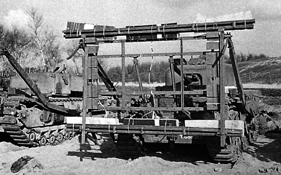
Churchill with Bangalore Torpedoes
Another project that involved the Calgary Regiment’s six tanks at Witley, was the trials carried out on a second explosive device based on the Onion framework. Two lengths of Bangalore Torpedo3 were fitted upright to the face of the “Onion” vertical framework. This was then dropped into light obstacles, such as barbed wire entanglements, which when detonated was supposed to clear a path through the obstacle. This explosive device was simply known as the “Churchill with Bangalore Torpedoes,” but as a result of poor performance during the trials, it was also considered a failure and never entered production.

Three (of six) Churchill tanks of The Calgary Regiment, at Whitley, Surrey. The “Churchill with Bangalore Torpedoes” is fitted to the furthest tank, while in the centre, a Churchill Mark IV tank, is fitted with the “Onion” explosive device. On the nearest tank, a Churchill Mark III tank, of No. 11 Troop, “C” Squadron, is the framework of the “Onion” explosive device, to which no explosives have been fitted. Note the outward-facing leg in the centre on the right side of the photo, which would be attached to the top right-hand corner of an “Onion” explosive device framework that is fitted to a tank that is not in the photo. Source: MilArt photo archive.

A Churchill Mark III tank of No. 11 Troop, “C” Squadron, The Calgary Regiment, at Whitley,
Surrey, fitted with two upright “Bangalore Torpedoes” to the face of the “Onion” vertical
framework. Source: authors’ collection.
Notes
- The British designed and built Infantry Tank, Mark IV, Churchill (A22).
- The 14th Canadian Army Tank Regiment (The Calgary Regiment (Tank)), along with the 11th Canadian Army Tank Regiment (The Ontario Regiment (Tank)), and the 12th Canadian Army Tank Regiment (The Three Rivers Regiment (Tank)), were the three ‘army tank regiments’ of the 1st Canadian Army Tank Brigade, all of which were equipped with the Churchill ‘infantry’ tank.
- A Bangalore Torpedo is made up of one or more connected metal tubes filled with explosives and equipped with a firing mechanism, especially for destroying barbed-wire entanglements, mine fields, etc., and consisted of 3-inch (8-centimetres) diameter pipe, issued in 20-foot lengths (6-metre).
Bibliography
Fletcher, David, The Universal Tank, British Armour in the Second World War, Part 2, Her Majesty’s Stationary Office, London, England, 1993.
Library and Archives Canada, Ottawa, Ontario, Canada
RG24, National Defence, Series C-3, Volume 14243, Reel T-12708 – War Diary of the 14th Canadian Army Tank Regiment (The Calgary Regiment (Tank)), Canadian Armoured Corps, from 1 February to 28 February 1943, Volume 25
The National Archives, Kew, Richmond, Surrey, United Kingdom
WO 165/132 – Appendix “U” – Experiments & Projects, of the Half Yearly Report on the Progress of the Royal Armoured Corps, Report No. 6 – 31 July to 31 December 1942
Tonner, Mark W., The Churchill Tank and The Canadian Armoured Corps, Service Publications, Ottawa, Ontario, 2011.
You can rate this article by clicking on the stars below
To read the fascinating story of Canadian use of the Churchill tank order this book at http://www.servicepub.com
by Clive M. Law
MAYER, Paul Anthony, Major – Chevalier of the Order of Leopold II with Palm and Croix de Guerre 1940 with Palm – Infantry (The Algonquin Regiment) – awarded as per Canada Gazette dated 31 August 1946 and CARO/6733 dated 2 September 1946. (NOTE: Canada Gazette has Paul Anthony and the typed citation had Paul Anthony with Anthony crossed out and Augustus printed in.)

Lt-Col P.A. Meyer
Recommended by Lieutenant-Colonel J.F.R. Akehurst, Commanding Officer, the Algonquin Regiment on 20 September 1945; approved by Brigadier H.P. Bell-Irving, Officer Commanding, 10 Canadian Infantry Brigade on 20 September 1945 and passed forward on 21 September 1945; approved by Major-General H.W. Foster, General Officer Commanding, 4 Canadian Armoured Division; approved by Lieutenant-General G.G. Simonds, General Officer Commanding, Canadian Forces in the Netherlands on 25 September 1945 and passed for action on 6 October 1945. The citation reads:
On 20 September 1944, [the] Algonquin Regiment was fighting in the area of Assende, south of the Belgium-Holland border. The enemy were holding the area north of this town in considerable strength with headquarters at Philipine, Holland. At 0830 hours, Major Mayer, Commander “D” Company, was ordered to try to outflank the defences to the east. Leading his Company personally he pushed up across the open country to Valk. So complete was the surprise achieved by this attack that they succeeded in capturing a rear echelon, including a complete pay staff. Establishing himself at this point, Major Mayer dug in and set up the defences but before consolidation was complete the company was subjected to a heavy barrage, followed by a counter-attack by self-propelled artillery and infantry. Exposing himself many times to enemy fire, he directed and encouraged his men so skilfully that they held their ground. The enemy was completely routed with 150 prisoners taken in the engagement. This action was one of many in the Belgian campaign during which Major Mayer distinguished himself by his bravery and sterling leadership and his exploits enjoy a very high reputation in his unit.1
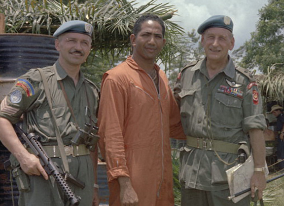
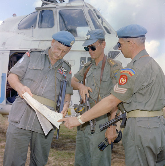
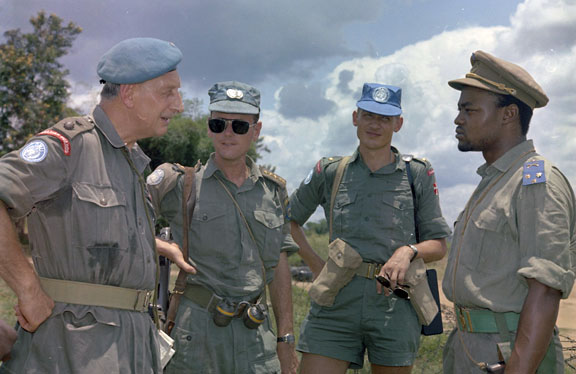
This series of photographs are from the Canadian Army official photos of the Congo mission. Taken shortly after the action for which Mayer was awarded the George Medal he is shown with the helicopter pilot (top) and the R22eR Sergeant who accompanied him. The other photos show UN officers involved in the planning and the helicopter that transported the mission members. MilArt photo archives
 Awarded George Medal as Lieutenant-Colonel Paul Augustus Mayer, MBE, CD as per London Gazette of 16 October 1964 and Canada Gazette of 03 October 1964 while serving with the Canadian Army in the Congo.
At one point Lt Col Paul Augustus Mayer, MBE, GM, CD, served as Chief Instructor at the Guards Depot and Senior Major of the 1st Battalion.
THIRD SUPPLEMENT TO
The London Gazette
OF FRIDAY, 12th FEBRUARY, 1954
The QUEEN has been graciously pleased, on the advice of Her Majesty’s Canadian Ministers, to give orders for the following promotion in, and appointments to, the Most Excellent Order of the British Empire, in recognition of gallant and distinguished services in Korea:—-
To be Additional Officers of the Military Division of the said Most Excellent Order :— Major Paul Augustus MAYER, C.D. (ZB 2864), The Royal Canadian Infantry Corps.
SUPPLEMENT TO
The London Gazette of Tuesday, 1 3th October 1964
CENTRAL CHANCERY OF THE ORDERS OF KNIGHTHOOD
St. James’s Palace, London S.W.I.
16th October 1964.
The QUEEN has been graciously pleased, on the advice of Her Majesty’s Canadian Ministers, to approve the award of the George Medal to the under-mentioned:
ZD 2864 Lieutenant-Colonel Paul Augustus MAYER, M.B.E., C.D., The Regiment of Canadian Guards.
On 24th January 1964 Lieutenant-Colonel Mayer was charged with the rescue operations of American and European Missionaries in Kwilu Province. On 27th January 1964 during a rescue operation at Kisandji this officer rescued two nuns and three priests. Eight nuns and one priest remained. He was requested by one of the priests to speak to the native chief in an endeavour to free the remainder of the Missionaries. During talks with the native chief council, Lieutenant-Colonel Mayer was hit on the back of the neck with a club and knocked unconscious. Members of the Jeunesse removed his revolver, beret and web belt. The council argued for killing him there and then. They informed him that if one shot was fired he and all the nuns would be killed. At this point, a frenzied Jeunesse thrust the pistol in his stomach and pulled the trigger. Fortunately there was no round in the chamber. In the meantime three priests and two nuns were able to board the helicopter. After arrangements had been made to free the remaining eight nuns, Lieutenant-Colonel Mayer was allowed to leave amongst a wild and screaming mob. During the whole operation, this officer’s life was in constant danger. His behaviour at all times was exemplary. His courage and composure was an inspiration to both the UN Personnel serving under him and also for the Missionaries. On several occasions he refused to leave his post until all Missionaries had been evacuated. He behaved at all times well above the call of duty and by his patience and energy in dealing with the members of the Jeunesse saved many lives.
More info cited in “Warrior Chiefs: Perspectives on Senior Canadian Military Leaders”, edited by Colonel Bernd Horn, Stephen Harris
Author,” I’ve Had Good Innings”, General House Publishing, Renfrew, ON, ISBN 1-89711336-6
OBITUARY
Paul A. MAYER
Born: 1916
Date of death : 2006-07-05
Wife : Pamela McDougall
MAYER, Paul A. Lt. Col. Retired, M.B.E., G.M., C.D. Peacefully at the Montfort Hospital on Wednesday, July 5, 2006 in his 90th year. Beloved husband of Pamela (nee McDougall). Loving grandfather of Crystal Mayer and David Mayer of Vancouver, B.C. He will be fondly remembered by his sister, niece and nephew, all of Melbourne, Australia. Friends may visit at the Central Chapel of Hulse, Playfair & McGarry, 315 McLeod Street on Monday, July 10, 2006 from 2 to 4 and 7 to 9 p.m. Funeral service will be held at St. Bartholomew’s Anglican Church, 125 MacKay Street, Ottawa, on Tuesday, July 11, 2006 at 11 a.m. As an expression of sympathy, memorial contributions to the C.N.I.B. or the V.O.N. would be appreciated. Published in the Ottawa Citizen from 7/8/2006 – 7/10/2006
Notes
1. From “Courage and Service” CD (Service Publications, Halliday and Blatherwick)
by Roger V. Lucy
In 1943, the War Office announced number of new small arms projects and asked Canada in which types it wished to participate. The Canadian crown corporation, Small Arms Ltd., (SAL) of Long Branch, Ontario (a neighbourhood of Toronto), responded with designs for a lightweight rifle, a machine carbine, and a self-loading rifle (SLR).
Lightweight Rifle
In August 1943, SAL was able to demonstrate its design of a lighter version of the No.4 rifle, to Major-General “Tubby” Lethbridge’s 220 Military Mission, which was touring North America looking into weapons and equipment for use in South-east Asia. The British required a lightened version of the .303 rifle, accurate out to 400 yards (360 metres). In light of this interest, DND’s Directorate for Small Arms and Vehicles (DVSA) undertook to have its further development funded by the Army Technical Development Board (ATDB).[1] Project 66 was approved on 15 December 1943. Two pilots were sent to the UK for trials, which took place at Bisley in early February 1944. The Canadian design lost out, and its British competitor was adopted as the No.5 (“Jungle Carbine”). Compared to the No.5, the British deemed the SAL rifle to be less accurate, had excessive muzzle flash, and required the manufacture of new components such as a new trigger group (which been redesigned by SAL as an improvement on the No.4) and shoulder pad. The pad was required to offset the extra recoil caused by the rifle’s lighter weight and shorter barrel – 6 3/4 lbs. (3 kg) and 22 inches (55 cm) respectively. The SAL rifle had a full length but lightened stock, held by two screws and accepted the No.4 spike bayonet.

SAL’s prototype for a lightweight version of the No.4 rifle. It lost out in competition to the British No. 5 Jungle Carbine. MilArt photo archives
Advised of an Indian requirement for 25,000 rifles, with specifications similar to its lightweight rifle, SAL undertook a redesign, incorporating some of the features of the British No.5. The prototype was completed in April 1944, but India adopted the No.5 rifle, which was now in production. Australia also trialed the first pattern Canadian lightweight rifle in August 1944. The Australians were impressed by the SAL rifle’s accuracy, handling and serviceability but deemed its excessive flash unacceptable. They also found it too light – particularly in the butt portion – for Australian methods of close-in fighting. In December 1944, SAL decided to halt further development. The lightweight rifle project was declared completed by the ATDB on 5 January, 1945.
Carbine, Machine, Canadian Experimental
When SAL had approached DVSA for funding for the development of a machine carbine, DVSA’s Director, Colonel J.L. McAvity advised SAL that, despite the stream of complaints from the field about the Sten, he could not get funding from the ATDB, unless the General Staff issued a requirement for a new machine carbine. SAL returned to the charge on 28 August, 1944 and McCavity obtained approval for the project at the ATDB’s September 5, 1944 meeting. This was based on a General Staff specification which called for a 9mm Parabellum, selective fire weapon with: satisfactory reliability in the most adverse conditions; weighing no more than 6 lbs. (2.7 kg) without a magazine; and capable, when firing single shots, to place five bullets in a 12 inch x 12 inch (30cm x 30cm) group at a range of 100 yards (90 metres). To improve accuracy, the cyclic rate was to be no more than 500 rpm. It was to have compact, short, 30-60 round magazines. To minimize stoppages, the magazine lips were to be incorporated in the body of the gun. The butt was to be removable, and the metal parts rust-proof. Finally – an aesthetic dig at the homely Sten – its appearance should inspire the user’s confidence.
The project got off to a slow start as SAL had been concentrating its development work on its self-loading, sniper and lightweight rifle designs. In December 1944, two of its designers George Kersey and Anton Rosciszewski, came up with an innovative “positive feed,” with the magazine mounted horizontally. A rocker arm worked by the bolt’s blow-back action, removed the round from the magazine, rotated it 90o, and chambered it. This arrangement protected the magazine and ammunition feed from dirt dust and sand – albeit at the expense, in early versions, of more misfeeds and ejection malfunctions. The trigger was based on a design Rosciszewski had developed for a modified Sten. Pressure on the top of the trigger fired the weapon in a fully automatic mode while pressure on the bottom of the trigger fired the weapon semi-automatically.

The Machine Carbine designed by Anton Rosciszewski of SAL, note the dual-action trigger which allowed selective fire. MilArt photo archives
The first pilot was completed in May 1945, and by the end of July it had successfully test fired 6,000 rounds. At that time a second prototype was under construction with modifications to bring it down to the specified 6 lbs. weight limit (loaded weight was in fact somewhat more than 7 lbs. – 3 kg), and the weapon had a fixed wooden stock, with a wooden fore-grip.
In October 1945 DND agreed to pay SAL $10,000 to build four more prototypes. Work continued after January 1946 when SAL was taken over by Canadian Arsenals Ltd, to become its Small Arms Division. In July 1946, the Inspection Board of the United Kingdom and Canada (IB) tested the experimental machine carbine against the Stens Mk. II and Mk. V. The experimental machine carbine had a lower cyclical rate of fire (492 rpm, against 610 and 534 respectively), and was more accurate, more tolerant of mud, somewhat less inclined to fire spontaneously when dropped, and was judged easier to carry and operate. However, it did have a notably higher rate of misfeeds. The project was sufficiently promising to be designated a long term one when the ATDB was disbanded at the end of 1946. In September 1948, it was trialed by the British Board of Ordnance against two experimental British designs, the EM2 and EM6. It performed very well (especially once the British solved its feed problems), but was deemed too long and heavy, lacked the folding butt of the EM2 and EM6 and, above all, was too expensive. Trials continued in Canada, it was tested in winter conditions at Churchill in the winter of 1948/49, but in the end the Canadian machine carbine, like the EM2 and EM6 lost out to the British Sterling submachine gun.
Self-loading rifles
As far back as September 1940, DND had monitored US developments of self-loading rifles , not only of the M1 Garand but also a Winchester project to develop an upscaled version of its M1 carbine, firing a standard full size cartridge (ATDB Project 18). While this passed Winchester’s own tests, it failed dismally when trialed at Aberdeen Proving Grounds in January 1943.

The 30 calibre Winchester Carbine being test fired. Note the addition of a bipod. MilArt photo archives

A worker at John Inglis Ltd., test firing the M1 carbine. MilArt photo archives
Based on a misapprehension of what the US M1 carbine actually was, the ATDB, at Lt.General McNaughton’s request, initiated Project 27 on 16 October, 1942 to investigate whether it could be developed as a Light or even Medium Machine gun. While it soon realized the error of its ways, 500 M1 carbines, and 150,000 rounds were obtained, and issued for trials by 4th Canadian Armoured Division in May and June 1943. They were issued to 4 Anti-tank Regiment, 4th Canadian Armoured Brigade Workshop and Divisional HQ, as a substitute for both pistols, for those issued side arms, and for other troops’ rifle. The former found it superior to their pistols in terms of range and accuracy; the latter found it more compact and easier to carry in confined spaces than the Lee Enfield. The only criticism was that it had far less stopping power than the Thompson SMG. In the end the M1 carbine was rejected because Lt.General McNaughton saw no requirement for it, and did not want to introduce a new type of ammunition into the supply chain.
No further work was done on SLR development in Canada until late in the War. DND’s views were largely guided by the initial British General Staff belief that semi-automatic rifles were of little utility, given the great increase in the number of machine guns that were being issued. Nonetheless, in April 1944 SAL initiated its own development- as a private venture – in response to a 1943 British specification for a gas-operated SLR with a rotating bolt and using a rimless 7.92 mm round. Design work began in November 1943, with the first pilot being ready for trials in June 1944. It used a dropping bolt locking mechanism similar to the Bren. To work properly this required very heavy parts and the design was declared obsolescent in January 1945. Its redesign was begun in March 1945 and test shot in May.

The SAL 7.92mm rifle was 45 inches long (115 cm), with two-piece wood furniture, a blade foresight with wind guard and peep type back sights, and a flash eliminator. It had a 10 round charger-fed magazine but could take a 20 round box magazine. It took the No.5 bayonet. Muzzle velocity was 2,500 f/s (750 m/s). MilArt photo archives

Test firing SAL’s 7.92-mm self-loading rifle. MilArt photo archives
The revised SLR had a forward locking bolt, and while considerably lighter was deemed too complex and delicate. A more robust version was developed with a threaded sleeve and – to give a more positive firing mechanism – hammer firing. This version was test-fired in August 1945. By December, the EX1, as it came to be designated, had successfully fired 800 rounds, and DND became seriously interested in the weapon – particularly as British efforts at designing a 7.92mm SLR were meeting with little success – tending to jam when firing British made ammunition.

The EX1 before work was switched to a design based on the .30 calibre T65 round. MilArt photo archives
The Director of Artillery recommended that further development be funded. SAL set about refining the design to reduce its loaded weight from 10 lbs. to 9 lbs. (from 4.5 to 4 kg), and to simplify manufacture, assembly and stripping the weapon. SAL expected to begin work on the pilot in January 1946 and have it ready by April. Soon thereafter the British changed their requirement to conform to the US T65 .30-06 round. While Small Arms Ltd had, by then, been wound up, the ATDB agreed, in July 1946, to fund work at Canadian Arsenals on a revised design, the EX2, which would not only accommodate the T65 round but further reduce weight – the goal being 7 lbs. (3.2 kg). The possibility of selective fire was also to be examined. Work on this weapon continued into 1950 – eventually, of course, it was the FN, firing 7.62 NATO that was selected.

Canadian Arsenals Ltd. EX2 prototype automatic rifle, chambered to the US T65 .30-06 round. MilArt photo archives


A variant of the selective fire version that CAL investigated. MilArt photo archives

A lightweight version of CAL’s EX2. MilArt photo archives
Notes
[1] For more information on the role of the ATDB in funding the development of new equipment see Secret Weapons of the Canadian Army, Service Publications 2006.
Bibliography
Lucy, R,V., Secret Weapons of the Canadian Army, Service Publications, Ottawa, 2006
Directorate of History and Heritage (DHH)
115.41013 (D17) Project 18 Self‑loading rifle
115.41013 (D65) Project 66 Lightened Rifle
Library and Archives Canada RG 24 Series C‑3
Reel C‑8386 file 8928‑11‑18 , Army Technical Development Board ‑ Project No. 18 ‑ Self‑loading rifle
Reel C‑8388, file 8928‑11‑66 Army Technical Development Board ‑ Project No. 66 ‑ Lightened rifles
Reel C‑8389, file 8928‑11‑907 ‑ Army Technical Development Board ‑ Project No. 907 ‑ Improved machine carbine
You can rate this article by clicking on the stars below
by Roger V. Lucy
A major threat to allied armour was the German Panzerfaust. Contrary to popular opinion the Panzerfaust (the name means armoured fist) was not a rocket-propelled grenade launcher, but disposable, one-man recoilless weapon. It used a black powder charge to discharge a large over-calibre fin-stabilized, hollow-charge warhead from a cast iron launching tube. The recoil from the discharge was counteracted by a three metre (10 foot) long jet of flame, vented out the back of the launcher. Introduced into service in mid-1943, as the Panzerfaust (Klein) or Gretchen, it was steadily improved. The Panzerfaust 30 (with an optimum range of 30 metres) had a larger warhead and longer launching tube. Subsequent versions, the Panzerfaust 60 and Panzerfaust 100 saw the optimum range increase to 60 and then 100 metres respectively. A re-loadable 150 metre version was going into production at the War’s end, but few if any, ever reached the front.) Overall, the Panzerfaust was a little over 1 metre (40 inches) long and weighed 6.8 kg (15 lb). By April 1944 Panzerfaust production had reached 200,000 per month, and 1.5 million per month by December. By May 1945, some 7 million had been delivered to the German armed forces and to para-military organizations such as the Volksturm and Hitler Jugend.[i]

An inert Panzerfaust 60 in the author`s collection, showing the complete round, and the actual fin-stabilized war-head

While relatively simple to use, and requiring little training, the Panzerfaust was not a weapon for the faint-heated. The fusing and its cylonite explosive (a TNT/RDX mixture) could be fickle. The range was short, and its rudimentary sighting arrangements made accuracy poor. The back-blast restricted where it could be used and betrayed the user (operational research indicated that users had a about 50% chance of surviving their attack on a tank). That said, if it struck a tank squarely, the Panzerfaust’s 14 cm diameter, 1.6kg warhead (5.5 inch, 3.5 lb) could penetrate 200 mm (8 inches) of armour. Traveling at 10,000 metres/second (32.800 feet/sec) the the molten metal jet by the shaped charge war-head was over 1.5 metres (4.9 feet) long. There are reports of Panzerfaust jets penetrating the 2 inch (50-mm) armour on the side of a Sherman, passing through intervening personnel and equipment to burn their way clean through the armour on the other side. If the jet encountered fuel and ammunition on the way the effects could be catastrophic.[ii] In Normandy, hollow-charge infantry weapons (Panzerfaust and Panzerschreck- a scaled up German version of the bazooka) accounted for about 6% of allied tank casualties, By the time the allies were advancing into Germany the proportion had reached 34%. The Panzerfaust also accounted for a significant proportion of the13,700 tanks and assault guns which the Soviets admitted to losing in 1945 – particularly in close-quarter city fighting. In December 1943, the Germans instituted the Panzervernichtungabzeichen (tank destruction badge) worn on the upper right sleeve. To win the badge the recipient had to destroy a tank with hand-weapons (grenades, mines, satchel charge, Panzerschreck or Panzerfaust). Some 14,000-18,000 were issued to those lucky enough to survive. In addition to the losses imposed, the ubiquity of the Panzerfaust placed heavy constraints on how and where armour was used and made close infantry/armour co-operation essential. Operational research concluded that concerns about the Panzerfaust threat slowed the pace of the allied advance east of the Rhine by about 30%.[iii]
Needless to say, troops tried to improvise whatever means they could to protecting their tanks from the effect of the Panzerfaust’s shaped charges. Extra track, wheels, storage bins, logs and sand bags were attached to the sides and turret in hope of disrupting the jet before it reached the tank’s main armour. The Russians tired welding wire-mesh frames, and even bed springs, to their tank turrets.
![These photographs illustrate the lengths to which tank crew would go in using spare tracks, from whatever source,in their search for extra protection against German shaped-charge and high velocity rounds.]](https://milart.blog/wp-content/uploads/2014/08/add-on-track-protection-4.jpg)
These photographs illustrate the lengths to which tank crew would go in using spare tracks, from whatever source,in their search for extra protection against German shaped-charge and high velocity rounds.]
In February 1945, First Canadian Army undertook a number of experiments using a derelict Sherman and captured Panzerfaust. These trials were later continued by Canadian Military Headquarters in cooperation with the British Directorate of Tank Design (DTD). Solutions tested included: spaced armour alone; spaced armour backed by a filler such as cork, rock-wool or sand; angled plates to prevent the shaped charges fuze from working correctly; spikes mounted in plastic armour – the aim was to perforate the shaped charge’s cone as it struck and deform the jet; and mounting mesh screens – the purpose of which was to catch the warhead gently enough to stop it without detonating it.

Sherman prior to trials.

A general view of how the screen protection was fitted for the trial.

A rear view showing the spacing of the double-meshed screen.

Panzerfaust projectile caught up in screen.
The final report issued by the DTD on 14 May, 1945 does not make encouraging reading.
Spaced armour had to be at least 30 inches (75 cm) from the main armour to defeat the shaped charge – increasing the overall width of the vehicle by 5 feet (1.5 metres). A 3/4 inch (20 mm) spaced armour plate with a stand-off distance of 12 inches (30 cm) or less actually enhanced the shaped charge’s effect by optimizing its stand-off distance. Spaced armoured backed with 12 inches of cork or rock wool did not work. Spaced armour filled with 12 inches of sand usually worked, but added 5 to 9 tons to the vehicle’s weight.

Here the Panzerfaust has struck low, blowing off the screen and penetrating the hull

A Panzerfaust is fired at a derelict Sherman, note the considerable back-blast.
Both angled plates and spikes showed promise against small rotating shaped charge shells, but not against heavy non-rotating charges such as the Panzerfaust 60 or the Stielgranate 41 round used with the 3.7 cm PaK 36. Mounting mesh screens worked to some extent with the relatively low velocity Panzerfaust (klein), which had a kinetic energy of only 440 ft/lbs. They failed to stop a Panzerfaust 60 with a KE of 3500 ft/lbs. It was not possible to devise a screen strong enough to stop the Panzerfaust 60, but gentle enough to prevent it from detonating.

A rear view showing the spacing of the double-meshed screen

More often it did not. Even so both the large and small Panzerfaust penetrated the tank’s side.
Using small charges to disrupt the jet- a forerunner of reactive armour – was also considered. It was deemed “wholly impracticable” – as it was impossible at the time to make the charges sensitive enough to detonate in time to defeat the shaped charge, but not so sensitive that they would not be set off by chance blows or near-by explosions. The British obtained similar results in trials carried out in Normandy and Italy. A Panzerfaust could burn through the frontal armour of a Churchill (175mm), and even with mesh screens mounted, had no trouble penetrating its 79 mm side armour.

The Germans also used mesh screens, the so-called Thoma Schürtzen, but their main intent was to protect the tank’s undercarriage from anti-tank rifle fire.
The final conclusion was that the only certain defence against the Panzerfaust was to ensure the closest possible co-operation between armour and infantry. Despite the apparent ineffectiveness of the various improvised counter-measures, the Germans believed they were having some effect. They had begun to attack armoured vehicles by firing two Panzerfaust in quick succession, one to blow away any screening, the other to penetrate the AFV. According to a German report of 6 April, 1945 the Panzerfaust 150 was designed to overcome countermeasures. Its sharply pointed cap helped penetrate any screening, and it had a semi-circular cavity to achieve even deeper penetration. The War ended before it entered service but it influenced post-war Soviet and West German designs.[iv]
The above illustrations come a report prepared Major A.G. Sangster, the AFV Technical Development Officer at HQ First Canadian Army.
Bibliography
Library and Archives Canada
RG 24 microfilm C-5773 file 55/508/9
RG 24 Volume 9392
Copp T. ed, Montgomery’s Scientists Operational Research in Northwest Europe, WLU. Waterloo, 2000
Gander, T.J Field Rocket Equipment of the German Army, Almark London 1974
Rottman G.L, Panzerfaust and Panzerschrek, Osprey 2014,
Weeks, J, Men Against Tanks, David & Charles, London, 1975
Notes
[i].Rottman G.L, Panzerfaust and Panzerschrek, pp 18-19,21, 28.
[ii]. Ibid pg. 54;Gander, T.J Field Rocket Equipment of the German Army, pp.55-6
[iii].Copp T. ed, Montgomery’s Scientists Operational Research in Northwest Europe, pp.553-60
[iv].Library and Archives Canada, RG 24 microfilm C-5773, file 55/508/9, RG 24 Volume 9392
You can rate this article by clicking on the stars below
The ‘Priest’ Kangaroo Armoured Personnel Carrier, in Canadian Service, 7 August to 30 September 1944
by Mark W. Tonner
Introduction
In North-West Europe, during the later half of 1944 and into 1945, the Canadian Army used two types of armoured vehicles that came to be known as a Kangaroo. The Kangaroo was the world’s first fully tracked ‘Armoured Personnel Carrier.’ This ingenious concept was devised by Lieutenant-General G.G. Simonds, the General Officer Commanding, II Canadian Corps, as he searched for a way to reduce the high casualty rate amongst his infantry. His solution also allowed them to move at ‘tank speed,’ along with their supporting tanks, from start line too final objective.

‘Priest’ Kangaroo armoured personnel carriers with troops of the 4th Canadian Infantry Brigade, 2nd Canadian Infantry Division aboard, on the evening of 7 August 1944 prior to the launch of Operation TOTALIZE. Source: 1 CACR Association & Archive.
Birth of the ‘Priest’ Kangaroo Armoured Personnel Carrier
Near the end of July 1944, General H.D.G. Crerar, General Officer Commanding-in-Chief, First Canadian Army, had instructed Lieutenant-General Simonds, to prepare plans for a breakthrough in the Canadian sector, telling Simonds to, “draw up plans for an actual attack, axis Caen-Falaise, objective Falaise” (Operation TOTALIZE, 7-10 August). On 31 July, Simonds verbally gave Crerar his appreciation of the situation and outline plan, with Simonds emphasizing that:
the ground is ideally suited to full exploitation by the enemy of the characteristics of his weapons. It is open, giving little cover to either infantry or tanks and the long range of his anti-tank guns and mortars, firing from carefully concealed positions, provides a very strong defence in depth”
On 2 August, Simonds put both his appreciation and outline plan on paper and sent it out to his divisional commanders. In his covering letter to the divisional commanders, Simonds wrote in part
“The infantry accompanying the armour to first objective in Phase One must go straight through with the armour. Arrangements have been made for about 30 stripped Priests’ chassis to be available to each of the infantry divisions (2nd Canadian and the British 51st (Highland)) operating in Phase One for this purpose …. The essentials are that the infantry shall be carried in bullet and splinter-proof vehicles to their actual objectives.”
This innovation was the first use of what have since come to be called armoured personnel carriers, in which infantrymen rode into battle mounted in vehicles with the same armoured protection and mobility as the tanks that accompanied them.

An example of the M7 ‘Priest’ 105-millimetre self-propelled gun, pictured here as No. 4 gun, “E” Troop, 78th Field Battery, 13th Canadian Field Regiment, Royal Canadian Artillery, 3rd Canadian Infantry Division, in Normandy, July 1944. This particular vehicle (S215830) was itself converted to a ‘Priest’ Kangaroo armoured personnel carrier, and subsequently was one of the initial 50 issued to the 1st Canadian Armoured Personnel Carrier Squadron, on 1 September 1944. Source: MilArt photo archive.
The concept of carrying troops into battle in specially adapted tanks had been tried as far back, as the Canadian Corps’ Amiens (France) offensive of August 1918, during the Great War of 1914-1919. Trials had been conducted in the United Kingdom during 1942-1943, in the use of armoured sleds carrying infantry, which were towed by tanks, and which was put into practice by the United States Army at Anzio (Italy) in early 1944. I Canadian Corps, at that time in Italy (1944), had also suggested the use of ‘stripped’ down universal carriers,1 towed by tanks, as armoured infantry carriers, in the attack. However, Operation TOTALIZE marked the first battlefield appearance, of specialized armoured troop-carrying vehicles of the sort, which had the same armoured protection and mobility as tanks.
On 31 July, Lieutenant-General Simonds sought to obtain American permission to modify the M7 ‘Priest’ 105-millimetre self-propelled guns, which were just being withdrawn from the 12th, 13th, and 14th Field Regiments, Royal Canadian Artillery, of the 3rd Canadian Infantry Division. These regiments had been equipped with the M7s for the Normandy landings, of 6 June 1944, and subsequent bridgehead battles, but were now turning these into Ordnance, upon being re-equipped with towed 25-pounder equipments.2
This permission being obtained, the urgent task of converting these equipments was set in motion. On the evening of 31 July, Brigadier G.M. Grant, Deputy Director of Mechanical Engineering, First Canadian Army,3 was instructed by Crerar, to set up an organization to convert 72 M7 ‘Priest’ 105-millimetre self-propelled guns to armoured personnel carriers by 9 August. This date was soon however changed to 6 August with “as many as possible” by the night of 5 August. At noon on 1 August, Major G.A. Wiggan,4 Officer Commanding, 2nd Tank Troops Workshop, Royal Canadian Electrical and Mechanical Engineers, was called to the Deputy Director of Mechanical Engineering office at First Canadian Army headquarters. Here he was instructed to carry out the task of converting these 72 M7 ‘Priest’ 105-millimetre self-propelled guns into armoured personnel carriers. Major Wiggan was instructed to set up an ad-hoc Advanced Workshop Detachment5 (code named ‘AWD Kangaroo’) to carry out these conversions.

‘Priest’ Kangaroo armoured personnel carriers, with troops of the 4th Canadian Infantry Brigade, 2nd Canadian Infantry Division aboard, on the evening of 7 August 1944, prior to the launch of Operation TOTALIZE. Note the driver’s vision aperture in the open position, with the driver seated above on the top of the upper front plate. Source: 1 CACR Association & Archive.
The conversions were to be made in such a way that the Priests could be converted back into self-propelled guns. The process consisted of removing the 105-millimetre gun, with mount and mantlet, and all artillery related equipment, and welding armour plate across the gap left by the removal of the gun. The interior ammunition stowage bins, and crew seating, was also removed, resulting in a spacious interior. The additional armour plating that the previous artillery crews had added along both sides of the fighting compartment, for added protection, was retained. At the same time the radial engine was subjected to an overhaul (the 100-hour check), the M7 ‘Priest’ having a 450-horse power Continental R975 radial aircooled 9-cylinder aircraft engine that required a thorough check after every 100-hours of operation (the overhaul itself would normally take seven days to complete). Finally, the vehicle was given a general serviceability check of the transmission, differential, brake linings and running gear. Keep in mind that at the time of conversion, the original M7 ‘Priest’ 105-millimetre self-propelled guns, had been in constant action, from their early June landings in Normandy, up until the decision was taken to convert them into armoured personnel carriers, leaving very little time, for proper maintenance by the artillery crews, due to the urgent need, and demands made on them to provide artillery support, too on going operations. By the time of conversion, these equipments, were in quite rough mechanical shape, and the urgency under which they were converted, left little time, but for the most basic of mechanical repairs, in order to have them serviceable for the forthcoming Operation TOTALIZE.
On 2 August, ‘AWD Kangaroo’ was established within the Rear Maintenance Area of 21st Army Group,6 in two fields near Bayeux, France. This was about twenty miles (32-kilometres) from the start line for Operation TOTALIZE. It consisted of elements of fourteen Canadian and British, electrical and mechanical engineering units,7 and consisted of 250 all ranks, 250 all ranks, who pooled their efforts and skills into the project. The first crews arrived late in the afternoon and, by last light, had 14 vehicles stripped.8 The hours of work established were from 5:00 to 11:00 A.M., and 12:30 to 5:00 P.M., and 6:00 to 10:00 P.M. daily, but with the urgency of the situation, 4:00 A.M. to 11:00 P.M., was the norm. All Canadian and British electrical and mechanical engineering units within First Canadian Army were canvassed for electric and gas welding equipment, along with the tradesmen to go with them. Unlimited access to welding rod, armour plate, radial engine parts, oxy-acetylene welding sets and gases and radial engine overhaul stands were required.

‘Priest’ Kangaroo armoured personnel carriers, carrying troops of the 4th Canadian Infantry Brigade, with tanks of the 2nd Canadian Armoured Brigade, on the evening of 7 August 1944, moving to their start line prior to the launch of Operation TOTALIZE. Source: 1 CACR Association & Archive.
The armour plate came from the ‘Help Yourself Park’ of “W” crocks (the name given to tanks salvaged from the battlefield that were declared beyond repair), and after this source was exhausted, steel plate from the Schneider Steel Works in Caen and from wrecked and stranded Naval craft on the beaches was tried. Both were found to be unsuitable, so mild steel ½-inch plate from the steel mills in the south of Caen was used. These plates were welded over the opening left by the removal of the gun, in the form of spaced armour, that is, one plate welded over the opening from the outside and one welded over the opening from the inside, with the space between the plates being filled with sand.
A brief description of the specifications of the ‘Priest’ Kangaroo Armoured Personnel Carrier
The ‘Priest’ Kangaroo hull, was constructed of rolled and cast homogeneous steel, of welded assembly, and was 19-feet, 9-inches in length, 9-feet, 9¼-inches wide, and stood at a height of 8-feet, 4-inches, with a ground clearance of 17 1/8-inches. The armour of the upper front plate was a ½-inch thick, that of the lower front plate was 2 to 4 ½-inches thick, well the sides and rear plates were also, a ½-inch thick. The interior of the hull was divided into two compartments, the fighting compartment, and the rear compartment (or the engine compartment) which housed the power unit (engine) and transmission gear. The driver’s position, was located in the left-front of the fighting compartment. The driver was provided with a large vision aperture, with a small vision port protected by very heavy glass, for use, when the large vision aperture was closed, although most drivers preferred to keep the large vision aperture open in all but the heaviest enemy fire. They felt it was not really safe to drive using the small vision port only, their field of view was too restricted and their vehicle was often used in rather tight quarters. The driver was also provided with a removable windshield which could be fitted into the large vision aperture, when operating the vehicle, with the aperture in the open position. A large box was provided for its stowage, when not in use, which was mounted to the driver’s left, on the inside, of the front armour plate. The driver carried out opening and closing of this aperture, from within the vehicle.

A rear view of troops ‘embussed’ (loaded) in a ‘Priest’ Kangaroo. Note the thickness of the upper left-side additional armour plating, and the ‘absence’ of the basic pioneer tools, except for a lone shovel, on the engine compartment top plates. This particular vehicle, saw service as the No. 4 gun, “F” Troop, 43rd Field Battery, 12th Canadian Field Regiment, Royal Canadian Artillery, of the 3rd Canadian Infantry Division, before conversion to that of a ‘Priest’ Kangaroo armoured personnel carrier. Source: 1 CACR Association & Archive.
Many of the ‘Priest’ Kangaroos retained their anti-aircraft/ground defence .50-calibre Browning heavy machine gun M2, heavy barrel, which was mounted in a ring mount, on the right-front corner of the fighting compartment, underneath which, on the hull side interior wall, stowage was provided for boxes of .50-calibre belted ammunition. About 60% of the ‘Priest’ Kangaroos retained their No. 19 wireless sets (a radio set) for communications. The No. 19 wireless set consisted of an “A” set for general use, and a “B” set for short range inter-tank work at the troop level, and an intercommunication unit for the crew. Access to the vehicle was gained by four pairs of grip bars, with two pairs being mounted on each side of the fighting compartment, which served as ladders to the fighting compartment. Access to the engine was provided through two engine compartment top plates, and through a set of rear engine doors, located below the rear plate of the upper hull. Located within the engine compartment, were four fuel tanks, with a total fuel capacity of 176 gallons. The ‘Priest’ Kangaroo had a road speed of approximately 25-miles per hour, and a cross-country speed of approximately 15-miles per hour. The suspension used on the ‘Priest’ Kangaroo, was the ‘Vertical Volute Spring’ type, which consisted of 12 wheels in six bogies, with three bogie assemblies per track. The two wheels in each bogie assembly were pivoted on arms against a vertical spring which was protected by the bogie carrying bracket. A return roller was mounted either on top of, or behind, the bracket, the entire bogie assembly forming a self-contained fitting unit.
External stowage bins and containers (for various tools,9 and equipment), were also provided for, along with the standard compliment of pioneer tools (shovel, crowbar, pickaxe, axe) and recovery/breakdown equipment (tow cable, jack and wood blocks) which were carried on all tanks. Four towing shackles were provided on the vehicle, two at the front, and two at the rear. A towing pintle was provided at the rear below the rear engine door, with a maximum towing capacity of 10,000 pounds.

Upon conversion, the majority of the ‘Priest’ Kangaroo armoured personnel carriers, retained the markings of the artillery regiments, with which they had served as self-propelled guns, as can be seen in this photo. The markings above (‘D1’) and below (‘43’) the right-hand headlamp, indicate that this vehicle saw previous service as No. 1 gun, “D” Troop, 44th Field Battery, 13th Canadian Field Regiment, Royal Canadian Artillery, of the 3rd Canadian Infantry Division. Source: 1 CACR Association & Archive.

Directly below the ‘allied recognition star,’ which is painted on the right side of the fighting compartment, can be seen two pairs of grip bars, which were used to gain access to the vehicle, with another two pairs mounted on the left side, in the same position. Source: 1 CACR Association & Archive.
The ‘Priest’ Kangaroo Armoured Personnel Carrier in service
By the evening of 5 August, the 72 carriers were ready (with four more ready at noon on 6 August, which were held in II Canadian Corps reserve). Lieutenant-General Simonds, divided these 72 completed ‘Priest’ Kangaroos among the 4th Canadian Infantry Brigade, of the 2nd Canadian Infantry Division, and the British 154th (Highland) Infantry Brigade, of the 51st (Highland) Infantry Division, for Operation TOTALIZE.10 Each ‘Priest’ Kangaroo could carry approximately 10-15 fully armed infantrymen and their equipment, who ‘embussed’ (loaded) and ‘debussed’ (unloaded), over their armoured sides. Drivers for these converted ‘Priest’ Kangaroos, where found from No. 9 Canadian Base Reinforcement Battalion (which held Canadian Armoured Corps, and Royal Canadian Artillery reinforcements) and from the personnel and reinforcements carried by “E” Squadron, 25th Canadian Armoured Delivery Regiment (The Elgin Regiment), Canadian Armoured Corps,11 and from among those artillerymen of the three field regiments of the 3rd Canadian Infantry Divisional Artillery who had operated them (who were now surplus to their respective field regiments, as they had converted to towed guns), each ‘Priest’ Kangaroo ending up with a crew of one man, the driver. To maintain the 36 ‘Priest’ Kangaroos allocated to 2nd Canadian Infantry Division, an ad-hoc ‘Kangaroo’ Light Aid Detachment,12 of 31 all ranks (drawn from numbers 32, 33 and 34 Light Aid Detachments,13 Royal Canadian Electrical and Mechanical Engineers) under Captain W.T.E. Duncan (formerly of No. 33 Light Aid Detachment, Royal Canadian Electrical and Mechanical Engineers ), was established to service 36 ‘Priest’ Kangaroos, for a supposed period of ten days to two weeks.
At 11:30 P.M. on 7 August 1944, for the first time in Canadian history, armour and infantry advanced to the attack with the infantry protected from the enemy small arms fire and shell splinters. At the same time they were able to keep up with their tank support, as all were moving forward on ‘tracks,’ at tank speed. This use of the ‘Priest’ Kangaroo armoured personnel carriers was an immediate success. The infantry was able to obtain their objectives without suffering heavy losses from the enemy’s defensive machine gun and mortar/shell fire, while traversing the ground from start line too objective. The advance confirmed the effectiveness of this new tactical weapon. The mobility provided to the infantry by the ‘Priest’ Kangaroo armoured personnel carriers, along with the armoured protection, resulted in fewer casualties and greatly increased morale. The ‘Priest’ Kangaroos also proved effective in the role of delivering supplies forward to the infantry, and in the evacuation of casualties to the rear.

One of the 36 ‘Priest’ Kangaroo armoured personnel carriers, allocated to the British, 51st (Highland) Infantry Division, for Operation TOTALIZE, carrying troops of the 7th Battalion, Argyll and Sutherland Highlanders, 154th (Highland) Infantry Brigade. Note the ‘HD 69,’ chalked onto the outside armoured plate welded over the opening left by the removal of the gun, which was used as a means of identifying what unit a ‘Kangaroo’ was carrying, for movement control purposes. The number ‘69,’ being the Arm-of-Service serial used by the 7th Argyll’s, within 51st (Highland) Infantry Division. Also of note, the sign in the lower right-hand corner of the photo, was used to indicate the location of the 7th Argyll’s battalion headquarters, when in a static location. Source: authors’ collection.
Their success in Operation TOTALIZE (notably, in the lowering of infantry casualties) was immediately followed up by their use during the continued drive on Falaise known as Operation TRACTABLE (14-16 August).14 It was quickly realized (as early as 20 August) however, that a stronger parent organization for these one-maned crewed carriers, and the ‘Kangaroo’ Light Aid Detachment, was needed, and so, on 28 August 1944, instructions were issued for the organization, on a temporary increment basis only, of 1st Canadian Armoured Personnel Carrier Squadron, Canadian Armoured Corps, and Light Aid Detachment 1st Canadian Armoured Personnel Carrier Squadron, Royal Canadian Electrical and Mechanical Engineers, under the direction of Headquarters First Canadian Army in First Canadian Army Troops Area. The temporary basis of the Squadron and Light Aid Detachment, was to be reviewed monthly.
Captain F.S. Corbeau, formerly of The Grey and Simcoe Foresters,15 was appointed Officer Commanding, 1st Canadian Armoured Personnel Carrier Squadron, and Captain W.T.E. Duncan16 (formerly the officer commanding the ad-hoc ‘Kangaroo’ Light Aid Detachment) was appointed Officer Commanding, the Light Aid Detachment 1st Canadian Armoured Personnel Carrier Squadron, Royal Canadian Electrical and Mechanical Engineers17 (with effect from 1 September). The squadron, and attached Light Aid Detachment, was formed as an increment to Regimental Headquarters, 25th Armoured Delivery Regiment (The Elgin Regiment), for the purposes of administration. Under the ‘Table of Organization’ issued on 24 August, the Squadron was to have four troops of 25 ‘Priest’ Kangaroos each, for a total of 100, and an overall personnel strength for the squadron of 131 all ranks. Again, the personnel were drawn from No. 9 Canadian Base Reinforcement Battalion,18 and from those qualified, of the 12th, 13th and 14th Field Regiments, Royal Canadian Artillery, of the 3rd Canadian Infantry Division.

A column of ‘Priest’ Kangaroos, carrying troops of the 7th Battalion, Argyll and Sutherland Highlanders, 154th (Highland) Infantry Brigade (although the chalked ‘HD’ is barely visible beside the number ‘69’), moving toward their ‘forming up point’ for the start of Operation TOTALIZE. Source: authors’ collection.
On 1 September, Captain Corbeau’s squadron, took over 50 ‘Priest’ Kangaroos19 (half of his authorized establishment), from “E” Squadron, 25th Armoured Delivery Regiment (The Elgin Regiment), from which, on 2 September, he divided the Squadron into four Troops, consisting of, No. 1 Troop – with 14 ‘Priest’ Kangaroos, No. 2 Troop – with 12 ‘Priest’ Kangaroos, No. 3 Troop – with 12 ‘Priest’ Kangaroos, and No. 4 Troop – with 12 ‘Priest’ Kangaroos, for which he only had 28 gunners (the designation used by the Royal Canadian Artillery, for a ‘Private), Royal Canadian Artillery, who were qualified ‘Driver Tank’, of which only 14 had any driving experience. With the help of borrowed personnel from “F” Squadron, 25th Armoured Delivery Regiment (The Elgin Regiment),20 on the night of 2/3 September, the Squadron moved, on it’s ‘tracks’, to a harbour area near Brionne, France, where they were to await instructions for a probable move back to Bayeux (France), to return to Ordnance their ‘Priest’ Kangaroos and be re-equipped with ‘Ram’ Kangaroo armoured personnel carriers. Once in harbour (Brionne), and while awaiting the order to proceed to Bayeux, to exchange their ‘Priest’ Kangaroos for the new ‘Ram’ Kangaroos, Captain Corbeau’s squadron, spent 3 to 7 September doing much needed maintenance. Since the night of 7/8 August, the ‘Priest’ Kangaroos had been in continuous use, supporting First Canadian Army operations in the drive toward Falaise and the closing of the ‘Falaise Gap’, there had been little time for proper maintenance to be carried out on them. However, late on the afternoon of 7 September, the Squadron received orders to move to Bolleville, France, and report to I British Corps, where Captain Corbeau learned that the Squadron would be taking part in the operation to capture Le Havre (Operation ASTONIA), in which operation they were to be involved with from 8 to 12 September, with the British 49th (West Riding) Infantry Division, and 51st (Highland) Infantry Division.

Two of the 36 ‘Priest’ Kangaroos, allocated to the British, 51st (Highland) Infantry Division (both of which appear to be empty), travelling ‘down’ the SINATRA route. This route had been cleared from the 154th (Highland) Infantry Brigade’s rear assembly area, forward to the brigade’s start line, by the British 274th Field Company, Royal Engineers, of the 51st (Highland) Infantry Division, prior to the launch of Operation TOTALIZE. Note the use of the Highland Division’s ‘HD’ and the number ‘49,’ which was the Arm-of-Service serial used by the 274th Field Company, on the route marker (SINATRA), in the lower right-hand corner of the photo. Source: MilArt photo archive.
On 13 September, the Squadron was ordered to concentrate at Bolbec, France, where tank transporters were to pick-up and move the ‘Priest’ Kangaroos to a harbour area near La Capelle (France). Upon arrival they came under command of 3rd Canadian Infantry Division for the capture of Boulogne (Operation WELLHIT). During this operation, the Squadron was split between the Stormont, Dundas and Glengarry Highlanders, and the North Nova Scotia Highlanders, of the 9th Canadian Infantry Brigade, with 20 ‘Priest’ Kangaroos allotted to each, during various phases of the battle, from 17 to 22 September. On 23 September, the Squadron received orders that they were to be included in the capture of Calais (Operation UNDERGO), again, under command of 3rd Canadian Infantry Division, this time carrying the 1st Battalion, Canadian Scottish Regiment, throughout operations on 24 and 25 September. On 30 September, orders were received from Headquarters, First Canadian Army, that all ‘Priest’ Kangaroos, were to be turned into a British Royal Electrical and Mechanical Engineers Workshop, in the Cassel (France) area. The Squadron’s ‘Priest’ Kangaroos were to travel to Cassel on their own ‘tracks’ where, once turned in, the drivers would proceed to Pierreval (near Rouen, France) where they were to pick-up new ‘Ram’ Kangaroo armoured personnel carriers from “F” Squadron, 25th Armoured Delivery Regiment (The Elgin Regiment). The issue of these ‘Ram’ Kangaroos was spread over 1-2 October. Once complete, on 2 October, the Squadron was ordered to concentrate at Mill, The Netherlands. Two troops made their way on their own ‘tracks’, while the other two troops traveled by tank transporter. Once at Mill, the Squadron came under command of VIII British Corps.
Within two weeks of 1st Canadian Armoured Personnel Carrier Squadron, having concentrated at Mill, The Netherlands, they were absorbed into the newly embodied 1st Canadian Armoured Personnel Carrier Regiment, Canadian Armoured Corps, while a British sister regiment, the 49th Armoured Personnel Carrier Regiment, Royal Armoured Corps, was also formed shortly afterwards. Each regiment was equipped with 106 ‘Ram’ Kangaroo Armoured Personnel Carriers, giving each regiment the capability of lifting an entire infantry battalion. A future article will deal with the ‘Ram’ Kangaroo Armoured Personnel Carrier, in Canadian Service, 3 October 1944 to 20 June 1945.

An example of a ‘Ram’ Kangaroo armoured personnel carrier, with which 1st Canadian Armoured Personnel Carrier Squadron, Canadian Armoured Corps, was issued over the period of 1-2 October 1944. Source: authors’ collection.
As a closing note, on 29 August 1944, approximately ten ‘Priest’ Kangaroos, were issued to the 4th Canadian Armoured Division, from their supporting ‘armoured delivery squadron’ (“D” Squadron, 25th Canadian Armoured Delivery Regiment (The Elgin Regiment)). These ten ‘Priest’ Kangaroos, were used as ammunition/supply/troop carriers, within the division, with at least one (based on photographic evidence) being converted into an ‘armoured command post,’ by Headquarters, 4th Canadian Armoured Brigade. Unfortunately, the details of the fate of these ten ‘Priest’ Kangaroos, is rather sketchy, since they were all surplus to the vehicle entitlements, of the units in which they served, and were not ‘officially’ counted against a unit’s vehicle holdings.
Acknowledgements
The author wishes to thank Miss Courtney Carrier, for proofing reading and offering constructive criticism, and comments, on my draft copies of this article, and Bill Miller, for his constructive criticism, and comments, and Clive M. Law, for providing photos from the MilArt photo archives, and for publishing this article, and lastly, my wife, Denise, for her never-ending support.
Any errors and/or omissions, are entirely the fault of the author.
Notes
- The Universal Carrier (commonly known as the Bren Gun Carrier), was a lightly armoured tracked vehicle, which served in many different roles. It had no overhead protection, and its armour plate only afforded protection against shell splinters and small-arms fire.
- The Ordnance, Quick Firing 25-pounder (or just 25-pounder), was the standard field gun, with which the three field regiments of a Canadian infantry division, and one, of the two field regiments of a Canadian armoured division, was equipped with.
- The officer responsible for the maintenance and repair of First Canadian Army’s equipment.
- Major Wiggan was subsequently awarded a Member, Order of the British Empire (MBE) for his command of the ‘AWD Kangaroo,’ with part of the citation, for which, reading “His enthusiasm, initiative and driving force contributed very materially to completing in three and one-half days what appeared to be an impossible task in the time available” (awarded as per Canada Gazette dated 17 March 1945, and Canadian Army Routine Order 5466 dated 19 March 1945).
- An advanced workshop detachment, was a portion of a workshop, which occupied a position forward of its parent workshop’s main location, when the necessity of the situation required it.
- The Rear Maintenance Area of 21st Army Group, at this time was located around the French city of Bayeux, in Normandy, and contained all the static administrative and maintenance units, supporting the Second British Army, and the First Canadian Army, which were the two armies that made-up the 21st Army Group.
- From the Canadian, Corps of Royal Canadian Electrical and Mechanical Engineers, and from the British, Corps of Royal Electrical and Mechanical Engineers.
- The first priority on 3 August 1944, was the completion of a ‘pilot’ model, for approval of its design, which reached Headquarters II Canadian Corps at 6:30 P.M., that evening, for Lieutenant-General Simonds’ inspection.
- Although, in the initial rush of the ‘conversion’ production, many of the deficiencies in the servicing tools of the original M7 ‘Priest’ 105-millimetre self-propelled gun equipments, were never corrected.
- The delivery and issue of which was carried out by “D” Squadron, 25th Canadian Armoured Delivery Regiment (The Elgin Regiment), the ‘armoured delivery squadron’ of the 4th Canadian Armoured Division.
- “E” Squadron, 25th Canadian Armoured Delivery Regiment (The Elgin Regiment), was employed as the ‘Corps armoured delivery squadron’ of 2nd Canadian Corps Troops, and held reinforcement tanks and men to supply the needs of the armoured units which came under command and/or control, of Headquarters 2nd Canadian Corps.
- A Light Aid Detachment, was made up of members of the Corps of Royal Canadian Electrical and Mechanical Engineers, and was attached to a unit, to assist the personnel of the parent unit in first line repair of its equipment, in so far as that repair was outside the capacity of the unit, to inspect unit equipment and supervise and advise on unit maintenance, to assist the unit in recovering its equipment when damaged or stranded, to assist liaison between the unit and second line workshops, and to advise the unit on technical matters.
- Numbers 32, 33 and 34 Light Aid Detachments, had been respectively attached to the 12th, 13th, and 14th Field Regiments, Royal Canadian Artillery, while they were equipped with the M7 ‘Priest’ 105-millimetre self-propelled gun.
- At the end of Operation TRACTABLE, of the 76 ‘Priest’ Kangaroos originally provided, 61 were still ‘battle worthy,’ while the remaining 15 were ‘recoverable vehicle casualties,’ mostly caused by mechanical breakdown.
- Formally, the 26th Army Tank Regiment (Grey and Simcoe Foresters), Canadian Armoured Corps, which had been disbanded on 1 November 1943, with all of its personnel being absorbed into Canadian Armoured Corps reinforcement units in the United Kingdom, as future reinforcements for Canadian Armoured Corps units, in the field.
- Captain Duncan was subsequently awarded a Member, Order of the British Empire (MBE), for his untiring efforts, outstanding initiative, resourcefulness, perseverance, and technical ability, under extremely adverse administrative and operational conditions, in maintaining a high standard of ‘battle worthiness,’ of the ‘Priest Kangaroos, in operations from Falaise to Calais (awarded as per Canada Gazette dated 17 March 1945, and Canadian Army Routine Order 5466 dated 19 March 1945).
- With an approximate overall personnel strength for the light aid detachment of 60 all ranks.
- Was a component reinforcement battalion of No. 2 Canadian Base Reinforcement Group, which was capable of holding approximately 1,500 reinforcements (of all arms and services).
- These ‘Priest’ Kangaroos had, by now, been stripped of radios, servicing tools, and pioneer tools, since initially first going into action on the evening of 7 August 1944, and for which, there was a dire shortage of spares parts.
- “F” Squadron, 25th Canadian Armoured Delivery Regiment (The Elgin Regiment), was employed as the ‘Army armoured delivery squadron’ of First Canadian Army Troops, and held reinforcement tanks and men to supply the needs of the armoured units which came under command and/or control, of Headquarters First Canadian Army Troops.
You can rate this article by clicking on the stars below.
by Roger V. Lucy
In late 1942, the Canadian Department of National Defence (DND)’s Directorate of Vehicles and Artillery (DVA) began work at No.1 Proving Ground in Ottawa on a small tracked vehicle using largely Jeep automotive components. DVA anticipated that there was a potential requirement for the smallest practicable tracked vehicle, for use by airborne troops and in the Pacific theatre. The project was formalized by the Army Technical Development Board (ATDB), on 10 January, 1943, as project 49, and assigned to its proponent DVA. The vehicle came to be referred to successively as: the Bantam Armoured Tracked Vehicle, the Light Recce Tank, and finally as the Tracked Jeep. Its envisaged roles included: intercommunication (running messages over contested ground), armoured reconnaissance, and engaging unarmoured troops in airborne and combined operations. Follow-on versions of the vehicle were to be amphibious, with twin propellers for water propulsion; although fully laden, it had a very low freeboard.

One of two surviving Tracked Jeep Mk.I pilots now on display in the Canadian War Museum’s Lebreton Gallery. This example may be Pilot No.2, which underwent extensive reliability trials at No.1 Proving Ground, in Orleans, Ontario (just east of Ottawa). MilArt photo archives
The pilot was demonstrated in Ottawa in May, 1943. On 7 June, it was decided that further development of the vehicle would have to take place in the USA, and that the General Staff Specifications and the pilot Tracked Jeep should be sent to a firm there. The logical choice for this was Willy-Overland in Toledo, The Canadian Department of Munitions and Supply (DM&S)’s Army Engineering Design Branch (AEDB) gave Willys a contract to construct five prototypes, working under DVA’s supervision. Willys would provide the power train components, while Marmon-Harrington was contracted to provide the running gear, and body and do the final assembly. On 8 July the pilot was sent to Toledo. En route, on 10 July, it was demonstrated at US Ordnance’s Aberdeen Proving Grounds, in Maryland. There, despite its rather makeshift nature, pilot Tracked Jeep performed quite well. Initially it evoked little interest among the allies (although DVA suspected that US Ordnance was inspired by the Aberdeen demonstration to begin development of its rival T-29 amphibious light tracked vehicle – also based on jeep components).

Three-quarter front view of the Tracked Jeep prototype, note the prominent front radiator. No.1 Proving Ground technicians assisted by Victoria Foundry, located in Hull, Quebec, essentially handcrafted the prototype. The original prototype of the Tracked Jeep (or Bantam Armoured Tracked Vehicle) was assembled at No. 1 Proving Ground in the latter half of 1942. The photographs of this prototype were taken on 7 May 1943. MilArt photo archives
The specifications and film footage of the Tracked Jeep’s trials was sent Canadian Military Head Quarters (CMHQ) in London, however the Commander of First Canadian Army Lt. General Andrew McNaughton could see no requirement for such a vehicle. More enthusiastic was Major-General “Tubby” Lethbridge, whose 220 Military Mission was visiting North America investigating looking into weapons and equipment for use in South-east Asia. He was shown the pilot and expressed his belief that the Tracked Jeep would be “of special value for jungle warfare” On 27 August, Lethbridge ordered five production models requesting that three be assigned to the UK, and one each to India and Australia for trials. Arrangements for this were complicated by the fact that the actual vehicles were being made in the USA. Canadian Mutual Aid (Canadian’s programme of military assistance to Britain and other allies) could not make purchases in US funds, while Lend-Lease only covered equipment that was in production for the USA. The problem was finally solved in April 1944, by buying the vehicles on the Canada Account, and giving them to the UK as a gift.

Crew compartment of the Tracked Jeep Mk.1, No. 1, photographed in June 1944. Note the driver is placed on the right side in accord with British practice. The co-driver operated a No.19 radio set (to be mounted under the dash) and a Bren light machine gun. MilArt photo archives
The pilot was lightly armoured, open-topped (the British wanted it have roof armour, DND did not consider this to be feasible, but did agree to increase the floor armour to 6 mm for added mine protection), front-engined tracked vehicle with a crew of two, It was armed with a Bren LMG, while a No.19 radio-set (the standard set used in Commonwealth AFVs) was fitted under the dash on the left side. Unlike the front-engined pilot, the prototypes produced at the Willys plant, in Toledo, Ohio, mounted the engine transversely at the rear, to reduce the vehicle’s length. A Hotchkiss-type suspension was used, with two sprung bogies, each with two double road wheels, and a sprung leading wheel on each side. To ensure good riding characteristics, the suspension was moved as far back as possible while the idler was at the front. The tracks were designed to have extremely good adhesion in soft mud, and the Tracked Jeep could climb a gradient of 40% (it was claimed that 70% was possible, if the vehicle were properly balanced) . A standard Willys engine was used but with a Carmazin radiator which was the same size as but gave better performance than the Willys desert radiator. Steering was by controlled differential.

Rear left side view of Pilot No.1, Toledo, Ohio. 23 May 1944. MilArt photo archives
Because its airborne role would make front-line maintenance difficult, the Tracked Jeep was intended to be able to go 2,000 miles (3,200 km.) with minimum repair or maintenance. The suspension was designed to run without lubrication. This need for low maintenance had to be balanced by the need to keep weight as low as possible. The solution was to design modular components, such as the drive train, or suspension units, which could be quickly replaced in their entirety.

This marked-up photo shows Pilot No.1, Toledo, Ohio. 23 May 1944. MilArt photo archives
Willys’ first prototype was completed in April 1944. It suffered some initial teething problems, including a propensity to shed its tracks. These were partially solved by increasing the road wheel diameter from 10 to 12 inches (25 cm to 30 cm). Once the pilot seemed to work satisfactorily, it was demonstrated at Toledo, Ohio on 23 May, 1944, to representatives of the Canadian Army and Department of Munitions and Supply and soon after to representatives of the British Army Staff; the US General Staff and US Ordnance. All were all duly impressed by its performance. At Lethbridge’s urging the pilot was dispatched to the UK on 7 July, 1944 after only a brief period of testing in Ottawa, to determine what modifications were required to make the Tracked Jeep fully amphibious.

Once the initial bugs were ironed out the Tracked Jeep was demonstrated to British, Canadian and American brass at the Willys Proving Ground at Toledo, Ohio on 23 May 1944. This right side view of the Pilot No.1 was photographed at the time. MilArt photo archives
Unfortunately, Lethbridge was out of the country at the time the Tracked Jeep arrived in the UK, and CMHQ could find no one else at the War Office who had any particular interest in the project. No one at CMHQ was very enthused by it either. CMHQ had assumed the Tracked Jeep was just that – a light tracked load-carrier. They were dismayed to receive what looked like a reinvention of the pre-war Carden-Loyd “tankette” (Canada’s only armoured vehicle in the 1930s). In September, Lt-General Stuart, CMHQ’s Chief of Staff told DND that CMHQ saw no Canadian General Staff requirement for the Tracked Jeep. When the representatives of the British Ministry of Supply’s finally got around to seeing the vehicle being tested at Bracknell, in late September, they were impressed by its vehicle’s capabilities, but, like CMHQ, could see no requirement for it. On 20 September, DND halted work on the further prototypes until the British could make up their minds on whether they wanted the Tracked Jeep, or not.

Three-quarter top front view showing driver and gunner in position and driver’s periscope. MilArt photo archives
The Tracked Jeep demonstrated superior cross-country performance over all sorts of terrain, particularly soft mud. Its hill-climbing ability was judged superior to all other light tracked load carriers, while its amphibious capacity was deemed adequate (despite its low freeboard). However, despite the intent that it operate with minimal maintenance, early trials in the UK and in Canada quickly revealed serious flaws in the design of the bogies and tracks. New sets were sent out by air, but their redesign delayed the dispatch overseas of pilots 3 to 5 until November 1944. General Lethbridge agreed that prototypes should not be sent to Australia or India until these flaws were ironed out. Trials in the UK and in Canada through the rest of 1944 and into the spring of 1945 showed continued weakness in the tracks, with failures to most of the track-shoes and the pins after 300 to 500 miles (500 to 800 km). There were also major suspension failures. Bogie axle shafts broke, while the bogies themselves wore out after 2,300 miles (3,700 km.) – despite most Canadian trials taking place over relatively benign snow-covered terrain. The transmission also failed after 1,400 miles (2,300 km.). In November 1944, in an effort to address the problems with the Tracked Jeep’s bogies, the ATDB approved Project 910 whose aim was to produce a pilot set of magnesium wheels for the Tracked Jeep. These had synthetic rubber tires, bonded directly to the metal. The wheels were completed and tested in August 1945. The wheels themselves performed well, the tires did not, rapidly shedding in use.

Major General Alec Gatehouse, Chief Administration Officer of the British Military Mission in Washington, checks out the Tracked Jeep during its 23 May 1944 demonstration. General Gatehouse had previously commanded the British 1st Armoured Division in North Africa. MilArt photo archives
British requirements had meanwhile shifted from a two-man; light-armoured reconnaissance vehicle to an unarmoured (except for mine protection to the floor) air-transportable (able to fit in a C-47 without removing any equipment) load carrier with a front engine. A Tracked Jeep Mk.II was therefore designed, which incorporated the changes made to the Mk.I’s running gear and had a projected load capacity of 3,000 lbs (1,500kg). The six pilots ordered by the British Ministry of Supply were now to be this version. Willys, however, was unable to work on the Mk.II, citing other commitments (building the Tracked Jeep’s American cousin the T-29). In late November 1944 an offer to construct the Mk.II prototypes for some $170,000 was received from Marmon Harrington. This was still under consideration when, on 29 November the British Ministry of Supply advised CMHQ that it was no longer interested in the Tracked Jeep and suggested Canada should “investigate other types of airborne AFVs for future development”. The requirement for the load carrying version was “now defunct”. The Ministry of Supply was even less enthused by the armoured version of the Tracked Jeep, suggesting that three prototypes be sent to Australia, New Zealand and India to see if they had any use for them.

In October 1944 Tracked Jeep Pilot No.5 underwent air-transportability trials in the USA. Here it is being backed into a Waco CG15A glider, ‘with extreme difficulty’. MilArt photo archives
CMHQ observed to Ottawa, on 4 December, that the Tracked Jeep Mk.I had great performance, but no one could find a practical use for it. As for the Mk.II, because they were being built in the USA, the British had doubts about Canada’s ability to effect their delivery in sufficient quantities before the War ended. Questions were raised about how the Tracked Jeep’s role differed from the “jungelized” version of the Canadian Armoured Snowmobile, which were also being developed by the ATDB, to meet another British requirement. Moreover, no solution had been found to the financial complication that, because it not being standard US equipment, it was not eligible for Lend-lease. The British were therefore more interested in US-made light amphibians such as the T-29 or the Weasel. In its response, DND argued that production of the Tracked Jeep Mk.II in Canada should present no problems and poured scorn on the capabilities of the Weasel and the T-29. The War Office did not, in fact, agree with the Ministry of Supply, and on 5 December, 1944, asked Canada to give top priority to developing the cargo version, and confirmed the order for six Mk.II prototypes. The contract to build them was concluded with Marmon-Harrington in early January 1945. Labour problems at the Marmon-Harrington plant, however, delayed their completion and the first prototype was only ready in July 1945 – justifying the Ministry of Supply’s concerns.

It was just possible to get the Tracked Jeep into a Hadrian (Waco CG-4) glider–after the track skirting had been removed-–but it was still too wide to allow it to be secured properly; and too heavy to be flown safely. MilArt photo archives
In March 1945, CMHQ suggested sending two Mk.I prototypes to First Canadian Army for field trials. First Canadian Army was initially interested, but by late April, it was clear that any requirement for them had evaporated. Given the obvious fragility of the equipment, it seems just as well that these trials did not happen. Pilot No.5 was used for air-transportability tests in the USA. With some shoe-horning (including removing the idlers), it was loaded into a C-47, and into CG-13A and CG-15A Gliders. The conclusion was that, in its present form, the Tracked Jeep Mk.I was not suitable for airborne use.

In the spring of 1946, a Tracked Jeep was sent up to Churchill, in Northern Manitoba to be tested in swampy sub-arctic conditions alongside the Muskrat and Mudcat (amphibious versions of the Armoured Snowmobile). MilArt photo archives
With the end of the War – and of any further need for jungelized equipment – a new role was needed for the Tracked Jeep. Not required by the War Office, the last Mk.II pilots were delivered by Marmon Harrington to No.1 Proving Ground in Ottawa. In the spring of 1946, one was sent up to Churchill, in Northern Manitoba to be tested in swampy sub-arctic conditions alongside the Muskrat and Mudcat (amphibious versions of the Armoured Snowmobile). Again the weaknesses of the running gear proved evident, and, by October, DVA was reporting excessive wear on the tracks. The project was deemed a long term one (i.e., to be continued eventually) when the ATDB was disbanded at the end of 1946. Surviving examples of both the Tracked Jeep Mk.I and Mk.II now reside in the Canadian War Museum, costly memorials to what seemed a good idea at the time.

Mk.II Tracked Jeep on display at the Canadian War Museum in Ottawa, Ontario. MilArt photo archives

A survivor at a military vehicle gathering at Knebworth, United Kingdom, in the mid-1980s. courtesy Larry Hayward
Bibliography
Library and Archives Canada, Record Group 24:
Volume 9366, file 38/ARM VEH/43;
Volume 9368, file 38/BAS REPTS/1/9;
Volume 9392 – photos excised from 55/611/P49;
Reel C-5778, file 55/611/P49;
Reel C-8387, file 8928-11-49.
You can rate this article by clicking on the stars below.
By Clive M. Law
The Canadian Army did not boast a large mechanised force in the years building up to the Second World War. They did, nonetheless, have a fleet of almost 200 vehicles, with most of these consisting of artillery tractors, 15 hundredweight (cwt) trucks and a medley of cars, motorcycles and other utility trucks.
The vehicle numbering system to this fleet varied considerably with the consistent element being the holding unit’s official abbreviation shown on the front door panel. This lack of consistency was addressed in a letter from Lt .P. Jolley to the head of the Directorate of Mechanization and Artillery Colonel N.O. Carr (often called No Carr by his detractors) in March 1937 after Jolley’s return from an Ordnance Course in England.

This 1919 Vulcan shows the markings applied to British Army vehicles. The photo is dated 1931. MilArt photo archives
A close-up of the Vulcan. The marking shows the truck belongs to the Mechanized Wheeled Experimental Establishment and was the 825th vehicle purchased in 1919. MilArt photo archives
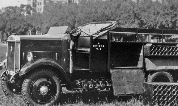
Earlier markings for truck number 2 of B Battery, 2nd Regiment Royal Canadian Artillery. MilArt photo archives
In addition to his more complete report to Headquarters, Jolley drafted a memorandum on 25 November 1936, outlining British practice in vehicle marking. In his memo he writes;
The following notes on the subject of the marking of military vehicles, based on instructions received during the 10th Ordnance Mechanical Engineer’s Course, 1934-1935, are submitted for your information;
Classification of vehicles
“A” vehicles – All tracked and semi-tracked vehicles and armoured cars.
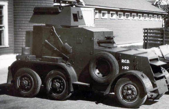
1935 armoured car showing the early mark. MilArt photo archives
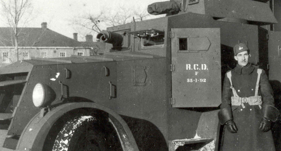
The same car as above but now with the new numbering style. MilArt photo archives
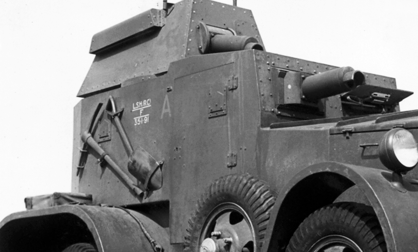
The second 1935 armoured car. Note the “A” classification. MilArt photo archives
“B” vehicles – All load and passenger carrying vehicles (all vehicles on pneumatic tyres except armoured cars).
Letters and numbers –
L – Lorry
M – Motorcar
C – Motorcycle
D – Dragon
T – Tank or Tractor
H – Half-track
A – Ambulance
V – Van
X – Trailer
Since, and including, 1933 numbers of “B” vehicles have been arranged to indicate the dates of purchase of the vehicle. The system of numbering provides for 999 new vehicles per year, as the maximum[i]. The series for 1936 is, accordingly 36001 to 36999.
The numbering portion was to be applied in white paint while the “A” and “B” classifications were to be in red.
The memo then showed a drawing of a British Army marking currently in use.
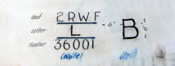
Jolley’s drawing of a British marking for the 2nd Battalion, Royal Welsh Fusiliers. The “L” denotes Lorry and the number denotes that this is the 1st vehicle purchased in 1936. MilArt photo archives
Carr passed the memo up the chain and included a hand-written comment, saying “I think this method is worth adopting”. By 11 December, this system was recommended to the Deputy Minister of National Defence and was approved by him for use in the Canadian Army in a 22 Januray 1937 letter. At the same time, the Deputy Minister ordered that the RCAF also standardize the markings on their motor vehicles.
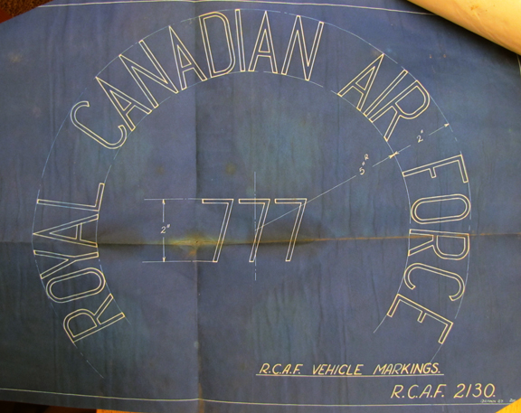
Proposed method of numbering RCAF vehicles. THere is little photographic evidence to show that this scheme was actually used. MilArt photo archives
To put the new scheme into effect Col Carr drafted a memo outlining the new system, stating;
The number to be allocated is now a Departmental matter. Hence it is recommended that numbers for all new vehicles be made to incorporate the year of purchase as a prefix, and that numbering be in accordance with the following series, year by year.
For Ordnance vehicles
1937 series – 37-1-1, 37-1-2, 37-1-3, etc.
1938 series – 38-1-1, 38-1-2, 38-1-3, etc.
For R.C.SA.S.C (Royal Canadian Army Service Corps) vehicles it is suggested that numbers might be as follows[ii]
1937 series – 37-1, 37-2, 37-3, etc.
1938 series – 38-1, 38-2, 38-3, etc.
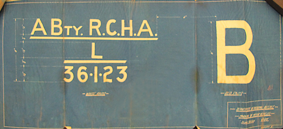
Technical drawing prepared to show the proper method of marking. MilArt photo archives
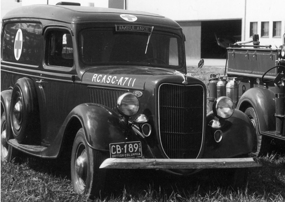
An ambulance with RCASC markings. MilArt photo archives
Carr concluded his memo with the comment that “vehicles already numbered should retain their original identification.” Notwithstanding this, photographic evidence shows that earlier vehicles were re-numbered.
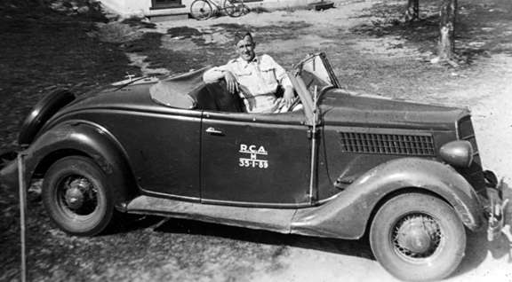
A 1935 Phaeton. Although this looks more suitable to its role as a roadster it was actually used as a field car. MilArt photo archives
This method of vehicle numbering remained in use through to 1942 for all Canadian Army vehicles in Canada. Vehicles used by the Canadian Army overseas adopted a new numbering scheme which will be addressed in another MilArt article.
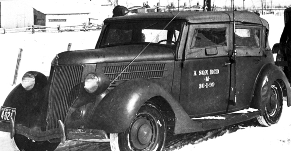
This 1940-plated vehicle belongs to “A” Squadron, Royal Canadian Dragoons and is marked as “M” for motorcar and 36-1-99 denoting the 99th vehicle purchased in 1936. MilArt photo archives
_______________________________________________________
[i] Although no one in the Canadian Army could have conceived purchasing more than 999 new vehicles in a single year, an unsigned minute, located at the foot of the memo, suggests that “the yearly serial number can be extended to any required extent.”
[ii] RCASC vehicles were those that were not operated uniquely by a unit as part of that unit’s establishment. These vehicles included buses, Stores lorries, staff cars and vehicles used in support of Base maintenance.
You can rate this article by clicking on the stars below.
by Clive M. Law
Shortly after the outbreak of the First World War the First Contingent of the Canadian Expeditionary Force (CEF) sailed for Britain with a small supply of motorcycles, cars and trucks. Many of these were privately owned and had been impressed into military service by the owners’ Commanding Officer.
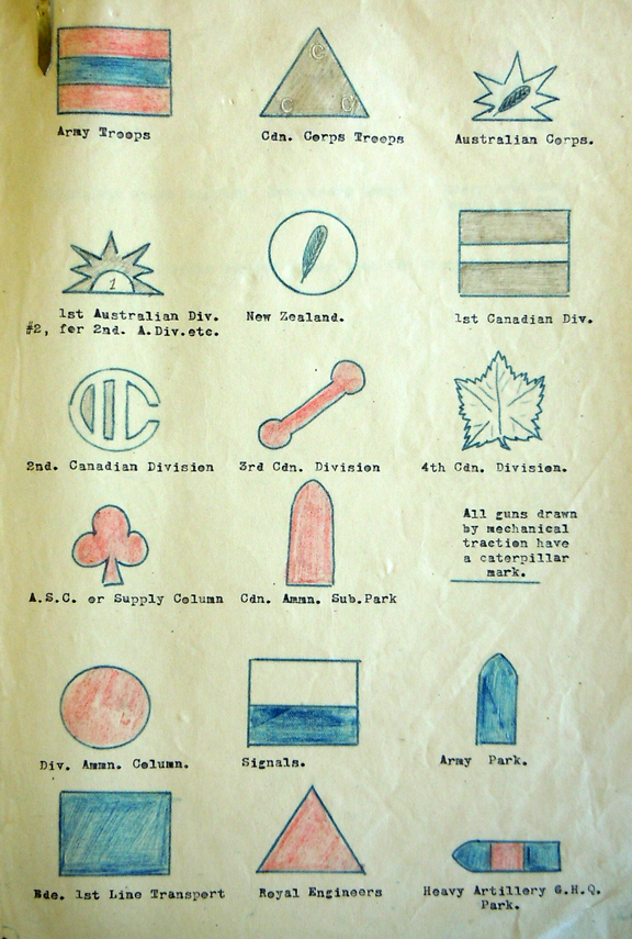
The first vehicle marking instructions were issued by the War Office and included the major formations as well as Commonwealth troops. MilArt photo archives
To support the Contingent the Department of Militia and Defence (M&D) made a small purchase of trucks to act as General Service Lorries and which were intended to follow the Canadian troops to France. The purchase was far from the War Establishment of an Infantry Division which called for 355 vehicles, used almost exclusively by the Ammunition Column and the Service Corps. With no domestic manufacturing capability headquarters found itself buying US-made vehicles. Ultimately, they bought vehicles from eight different suppliers. Worse, many of the trucks purchased were unsuited for their role and suffered early breakdowns while in England. Aggravating the situation was that spare parts for these trucks could only be obtained in the US. Once the War Office saw the state of the Division’s Mechanized Transport (MT) they undertook to replace the vehicles with those that met War Office (WO) specifications. Even then, there were six different makes amongst the 51 trucks supplied by the British.
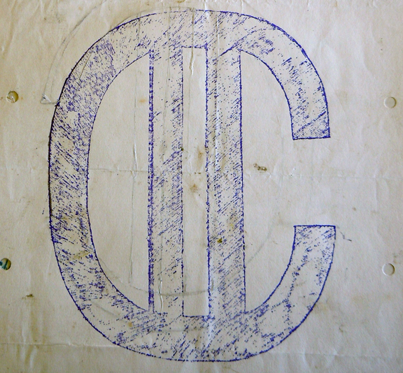
Official drawing of the 2nd Canadian Division’s “C-Two” mark. This copied the division’s battle patch as worn by officers. MilArt photo archives
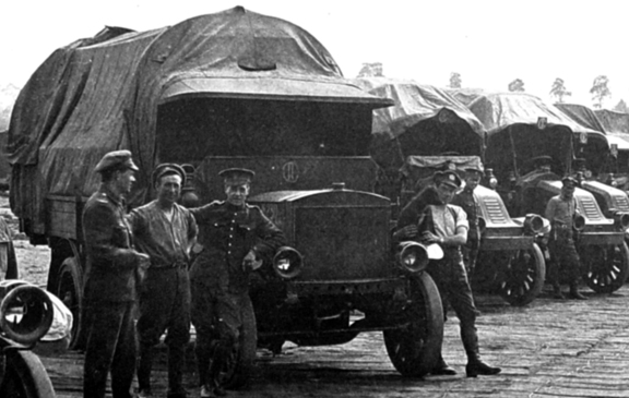
Note the “C-Two” identification plate, shown here above the cowl on the nearest truck, and attached to the cab roof on the others, MilArt photo archives
In keeping with the wishes of the War Office, the Canadians obtained additional trucks which met with British General Service (GS) specifications. These were acquired by either purchasing the trucks from the British trade or, once in France, indenting for their needs to British Army headquarters. By the time the Armistice was signed, the CEF held in excess of 3,000 vehicles, most of which were transport lorries with a small sprinkling of cars, ambulances and motorcycles.
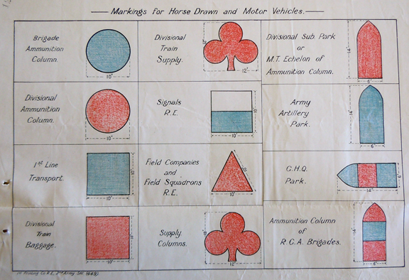
Following the designs suggested for the higher formations instructions followed for marking vehicles in lower formations. MilArt photo archives
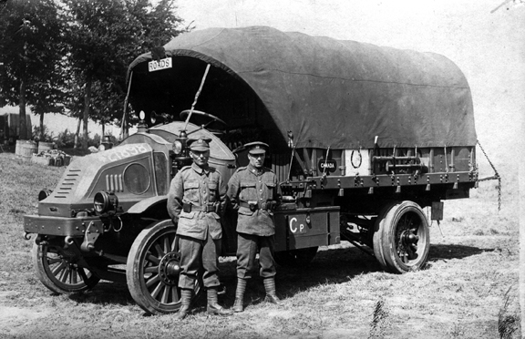
This Kelly Springfield shows a trefoil signifying that it is from a Supply Column. The sign is carried on the cab roof as well as on the side. The “Canada” is unofficial while the meaning of the “Roads” plate is unknown. Milart photo archives
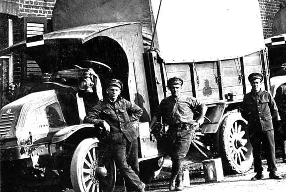
Another Supply Column vehicle but with a cab-roof plate showing that it is from the 1st Canadian Division. MilArt photo archives
Late in the war the War Office determined that vehicles needed to be better identified for both ownership and purpose. At the time horse-drawn equipment carried no marks and, with no established system from which to draw upon, the War Office put forth a scheme consisting primarily of graphics. Some of these graphics were already in use as Army, Corps or Divisional marks while others had been put into use to identify the type and nature pf supplies headed to the front lines. Lastly, a graphic could be used in different colours or colour combinations. The use of these vehcile markings was also extended to horse-drawn equipment.
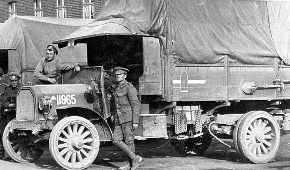
Another 1st Canadian Division vehicle, this one marked to an ammunition park. MilArt photo archives
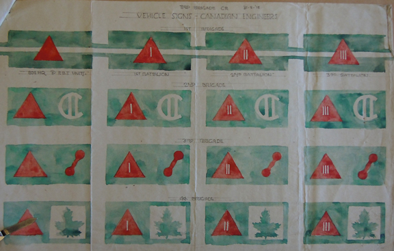
As the war progressed vehicle markings were further refined. This scheme, specific to the Canadian Engineers, was introduced in late August 1918. The format has a plain triangle for Brigade HQs and the addition of a vertical bar for each Battalion. The other devices identify the specific Division. MilArt photo archives
With most of these vehicle marks coming into use in the last year of the war it is not surprising that few photos of these exist.
You can rate this article by clicking on the stars below
by Mark W. Tonner
Introduction
The Cruiser Tank, Mark V, Covenanter (A13 Mark III), was the fifth ‘mark’ in a series of British designed and built cruiser tanks, and was the third ‘mark’ in the A13 series of British cruiser tanks. The A13 series consisted of, the A13 Mark I, the A13 Mark II, and the A13 Mark III, which respectively were the third, fourth, and fifth marks of British designed and built cruiser tanks. The earlier, first and second marks of British cruiser tanks, were the A9 series (A9 Mark I and A9 Mark I Close Support), and the A10 series (A10 Mark II and A10 Mark IIA).
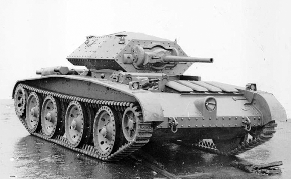
The initial Cruiser Mark V Covenanter (A13 Mark III) pilot model, armed with the 2-pounder Ordnance Quick Firing gun, and co-axial 7.92-millimetre Besa machine gun, mounted in the turret front, and the second 7.92-millimetre Besa machine gun, mounted in the driver’s position, which was dropped from production vehicles, due to the limited space left for the driver, when mounted. Source: IWM (KID 772).
In 1936, when considering the future requirements of tanks within the British Army, the British War Office, came to the conclusion, that two tank types would be required in future conflicts, one type being the ‘infantry’ tank, and the other type being the ‘cruiser’ tank. The ‘cruiser’ tank was designed with speed in mind, as their role was envisioned, as that of going through the gaps in the enemies defences created by the infantry and ‘infantry’ tanks, in the attack, and exploiting behind the enemy line, into his rear areas, in order to engage his tanks held in reserve, and to cut his lines of supply and communications. The British concept behind these two types of tanks, came from their experiences during the Great War of 1914-1918, where tanks had developed as infantry support weapons, hence, the concept of the ‘infantry’ tank. On the other hand, the concept of the ‘cruiser’ tank, came about from the traditional role of their cavalry during much of the conflict, that of waiting for a breakthrough to be achieved by the infantry, so that they could ride deep into the enemies rear areas and cut his lines of supply and communications.
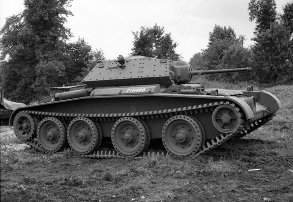
An example of a standard production Covenanter I, bearing the British War Department number T15488, and armed with the 2-pounder Ordnance Quick Firing gun, and co-axial 7.92-millimetre Besa machine gun. This particular tank, was built under Contract No. T.7218, by Leyland Motors Ltd., at their Kingston-upon-Thames works (London, England). Source: IWM (H 12377).
A brief note on the nomenclature (names) used by the British for the various ‘marks’ of the Cruiser Tank, A13 series. Prior to June 1940, the three ‘marks’ of the Cruiser Tank, A13 series, had simply been known, as the A13 Mark I, the A13 Mark II, and the A13 Mark III, respectively. As of 11 June 1940, British tanks were broken down into three classes as either, ‘light,’ ‘cruiser,’ or ‘infantry,’ by which,
– the A13 Mark I, became the Cruiser Mark III
– the A13 Mark II, became the Cruiser Mark IV (or Cruiser Mark IVA, the letter ‘A’ denoting a change in armaments)
– the A13 Mark III, became the Cruiser Mark V (or Cruiser Mark V* (the asterisk denoting service modifications to the engine cooling system), or the Cruiser Mark V** (the two asterisks denoting that the engine cooling system modifications were built-in).

An illustration of the front end view of the Meadows Flat 12-cylinder 300-horsepower gasoline engine, taken from the 1941 First Edition of the Tank, Cruiser Mark V Instruction Book, as prepared by London, Midland and Scottish Railway Company. Source: authors’ collection.
As of July 1941, the nomenclature of British tanks was changed again, as the British War Office began allocating type names to tanks, to make designations easier. Under this,
– the Cruiser Mark V, became the Covenanter I
– the Cruiser Mark V*, became the Covenanter II
– the Cruiser Mark V**, became the Covenanter III
– and the name Covenanter IV, was assigned to those tanks built to Covenanter III production standards, but with additional built-in engine cooling system modifications.
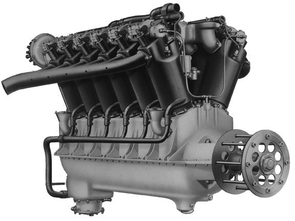
An example of the Liberty V12-cylinder 340-horsepower gasoline engine. Note the height and slimness of this engine, as compared to the flat and spread-out nature of the Meadows Flat 12-cylinder 300-horsepower engine. Source: authors’ collection.
A brief description of the Cruiser Tank, Mark V, Covenanter (A13 Mark III)
The Cruiser Tank, Mark V, Covenanter (A13 Mark III), came about, in early 1939, when the British General Staff, directed London, Midland and Scottish Railway Company, of Crewe, Cheshire, to design a new cruiser tank, which was to be known as the Cruiser Tank, Mark V, Covenanter (A13 Mark III). The requirements issued by the General Staff, on 2 February 1939, specified, that the A13 Mark III, was to have a maximum armour thickness of 30-millimetres (later increased to 40-millimetres), it was to be armed with the 2-pounder1 Ordnance Quick Firing gun, and a co-axial 7.92-millimetre Besa machine gun, it was to retain the Christie suspension system2, as used on the earlier A13 Mark I, and the A13 Mark II, and it was to have a lower overall height, then that of the A13 Mark I, and A13 Mark II3.

A general view of Covenanter tanks at various stages of production on the assembly line of a factory, somewhere in the United Kingdom, 1941. Source: IWM (P 174).
On 17 April 1939, with the threat of war with Germany imminent, one pilot model (Contract No. T.7077) and 100 production vehicles (Contract No. T.6931) were ordered straight off the drawing board, more or less, of London, Midland and Scottish Railway Company. Production of the Cruiser Tank, Mark V, Covenanter (A13 Mark III), was split between London, Midland and Scottish Railway Company, Crewe, Cheshire, English Electric Valve Co., Stafford, Staffordshire, and Leyland Motors Ltd., at their Kingston-upon-Thames works, with deliveries of production vehicles, beginning in November 1940. The last order for 196 Cruiser Tank, Mark V, Covenanter (A13 Mark III), was placed in August 1941. After the initial order of 17 April 1939 (for one pilot model, and 100 production vehicles), an additional 15 production contracts, totalling 1,771 vehicles were placed, and spread between London, Midland and Scottish Railway Company, the English Electric Valve Co., and Leyland Motors Ltd., for the Cruiser Tank, Mark V, Covenanter (A13 Mark III).
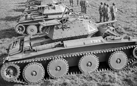
A Covenanter Close Support, bearing British War Department number T7117, which was built under the initial contract for 100 production vehicles (Contract No. T.6931), as a standard production Covenanter I, by London, Midland and Scottish Railway Company, which since production, was converted to a Covenanter Close Support, by the replacement of the 2-pounder Ordnance Quick Firing gun, with that of a 3-inch Howitzer Ordnance Quick Firing gun, and the retention of the co-axial 7.92-millimetre Besa machine gun. Note the turret full-width top hatch, in the open position, and the driver’s hatch, consisting of a hinged two piece rear section and a small hinged front section, which is folded down in the open position. Also of note, on the right side of the turret, is the Lakeman anti-aircraft mount, with the anti-aircraft/ground defence .303-inch Bren light machine gun connected to it. This particular tank, is seen here in British service with ‘A’ Squadron, 15th/19th The King’s Royal Hussars, 9th Armoured Division, in the fall of 1941. Source: IWM (H 15182)
The Covenanter, had a crew of four (commander, gunner, loader, and driver), it had an approximate battle weight of 18 tons, it was 19-feet, 3/8-inches in length4, and was seven-feet, 3 ¾-inches in height (which made its profile lower then that of the A13 Mark I, and A13 Mark II tanks, by one-foot, 2 ¼-inches), and was eight-feet, 6 ¾-inches wide. It was armed with a 2-pounder Ordnance Quick Firing gun Mark IX or Mark X, and a co-axial 7.92-millimetre Besa machine gun, both of which were mounted in the turret front. Initially, a second 7.92-millimetre Besa machine gun, was to have been mounted in the driver’s position, but this was dropped from production, due to the limited space left for the driver, when mounted. A .303-inch Bren light machine gun, which could be mounted on either side of the turret, for anti-aircraft/ground defence, was also provided. Also, a 2-inch bomb thrower was fitted into the right front turret roof, for the firing of smoke bombs, for the laying of a smoke screen. It had a maximum armour thickness of 40-millimetres, and a minimum armour thickness of 7-millimetres. Steel, instead of aluminum, was used in the production of the road wheels. Riveted construction instead of welding, was used, vertical surfaces were avoided, which resulted in an almost flat hull. Even a new lower turret was designed, which resembled a ‘squashed’ version of the type used on the A13 Mark II, although in reality it was a completely new design, though still mounting a 2-pounder, and co-axial 7.92-millimetre Besa machine gun. The turret was fitted with a full-width top hatch, which became known as a ‘sunshine roof,’ which opened horizontally, and slid backwards on parallel link arms.

Front view of a Covenanter IV, of Headquarters, 1st Canadian Army Tank Brigade, armed with the 2-pounder Ordnance Quick Firing gun, and co-axial .7.92-millimetre Besa machine gun. The barrel of the anti-aircraft/ground defence .303-inch Bren light machine gun, connected to the Lakeman anti-aircraft mount, can be seen, just above the driver’s right shoulder, and behind it, the spotlight, which was standard on British tanks of the period, and in the case of the Covenanter, was mounted on the right-side of the turret. The number ‘171,’ which appears on the right-front track guard, is the Arm of Service marking, by which vehicles belonging to Headquarters, 1st Canadian Army Tank Brigade, were identified, from August 1941 to May 1943. This Arm of Service marking, consisted of the number ‘171,’ in white, centrally located on a horizontally divided blue over brown coloured square. The white square, directly below the headlamp housing, is the centre portion, of the ‘Armoured Fighting Vehicle Recognition Sign,’ which was used as a form of “National Identification” marking for British and Canadian armoured fighting vehicles, of the period. It consisted of a 10-inch high by 18-inch wide rectangle, which was divided vertically into three 6-inch wide red/white/red strips. Source: MilArt photo archive.
Internal stowage bins for 109 rounds of 2-pounder ammunition, 18 boxes of 7.92-millimetre ammunition5, 26 rounds of 2-inch Bomb, smoke, and 600 rounds of .303-inch ammunition6, along with other miscellaneous items, were provided for. Like most other British tanks in service at this time, external stowage bins and containers (for various tools, and crew equipment), were also provided for, along with the standard compliment of pioneer tools (shovel, crowbar, pickaxe) and recovery/breakdown equipment (tow rope, jack and wood blocks), which were carried on all tanks.

A Covenanter IV, of Headquarters, 1st Canadian Army Tank Brigade, passing troops of an unidentified Canadian unit, while on exercise, somewhere in the United Kingdom. Source: MilArt photo archive.
The Covenanter, was powered by a Meadows Flat 12-cylinder 300-horsepower gasoline engine, and had a maximum speed of 31-miles per hour, and a cross-country speed of approximately 25-miles per hour. Three interconnected fuel tanks were located in the engine compartment, one on either side of the engine, and one below the engine, and an auxiliary fuel tank, which was mounted on the exterior of the rear hull, which was connected to the main fuel system, but could be jettisoned from the tank in an emergency7. Because a Meadows Flat 12-cylinder 300-horsepower gasoline engine was used, instead of the Liberty V12-cylinder 340-horsepower gasoline engine, as used in the earlier ‘marks’ of the A13 series, the engine cooling radiators could not be fitted into the engine compartment, at the rear of the tank. Instead they had to be mounted in the front-left of the tank, which meant that he drivers’ compartment, was moved to the front-right of the tank, with the radiators to his left. The mounting of the radiators at the front of the tank, instead of in the engine compartment at the rear of the tank, resulted in constant overheating along with other mechanical problems. In order to rectify the cooling system problem, various modifications were required in subsequent production vehicles, in order to correct the vehicle’s overheating, which in the end, was never satisfactorily overcome8.

T18368, a Covenanter I, which was issued to Headquarters, 1st Canadian Army Tank Brigade, on 5 August 1941, taking part in the filming of a British Military Training Film, entitled ‘Ten Tips for Tackling Tanks,’ in the fall of 1941, for which the crew is dressed as a German tank crew. The Covenanter driver’s compartment was notably cramped, as is illustrated here, note, there isn’t too much room between the driver, who is leaning on the folded down hinged front section, and the hinged two-piece rear section, of his hatch. Note the short pipe, on the turret side, just behind the driver, this was for the barrel of the anti-aircraft/ground defence .303-inch Bren light machine gun, to rest on when connected to its Lakeman anti-aircraft mount (a portion of which is visible), when not in use. The number ‘2,’ which appears midway along the turret side, indicates, that this is the number two tank of brigade headquarters (see the next caption for details). Source: authors’ collection.
The ongoing issues with the cooling system, brought about the Cruiser Tank, Mark V, Covenanter (A13 Mark III), being deemed unfit for foreign service, though it was used to equip armoured formations based in the United Kingdom for training purposes. However, improvements incorporated into the Cruiser Mark V** Covenanter III, and the later Covenanter IV, did deem these fit for foreign service, ‘in an emergency.’
The Cruiser Tank, Mark V, Covenanter (A13 Mark III) in Canadian service
The 1st Canadian Army Tank Brigade, commanded at that time by Brigadier F.F. Worthington, was the first formation of the Canadian Armoured Corps (CAC) to arrive in the Untied Kingdom, landing on 30 June 1941. The General Officer Commanding, Canadian Corps (VII Corps), Lieutenant-General A.G.L. McNaughton had been anxious to add an armoured formation to his force in the Untied Kingdom at the earliest possible moment, and had encouraged the authorities in Canada to hasten the departure of Brigadier Worthington’s, 1st Canadian Army Tank Brigade as much as possible. The brigade came under command of the Canadian Corps immediately upon its arrival in the United Kingdom. At this time, the brigade consisted of the following units:
Headquarters, 1st Canadian Army Tank Brigade, CAC
1st Canadian Army Tank Brigade Headquarters Squadron (The New Brunswick Regiment (Tank)), CAC
11th Canadian Army Tank Battalion (The Ontario Regiment (Tank)), CAC
12th Canadian Army Tank Battalion (The Three Rivers Regiment (Tank)), CAC
14th Canadian Army Tank Battalion (The Calgary Regiment (Tank)), CAC
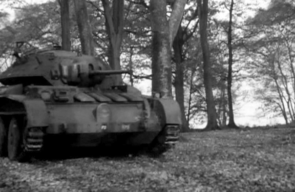
Another view of T18368, while taking part in the filming of ‘Ten Tips for Tackling Tanks.’ The ‘F2,’ in the centre of the nose plate, directly below the headlamp, indicates, that this tank is the number two tank of the ‘Fighting Group’ (commonly referred to as the ‘Fighting Troop’) of the brigade headquarters, with the other three tanks bearing the markings ‘F1,’ ‘F3,’ and ‘F4,’ respectively. To the left of the ‘F2’ marking, can be seen the Arm of Service marking (‘171’) of the brigade headquarters, as explained earlier. The marking that appears above left, of the Arm of Service marking, is that of the Formation sign (by which the formation that the unit operating the vehicle belonged to, was identified), used by the 1st Canadian Army Tank Brigade, from mid August 1941 to mid October 1942, which consisted of a gold or yellow maple leaf centred on an eight-inch by ten-inch square black background, with a black left-facing image of a ram superimposed centrally on the maple leaf. Source: authors’ collection.
1st Canadian Army Tank Brigade was to have been equipped with the Canadian-built Infantry Tank, Mark III, Valentine, before leaving Canada. However, because of delays in Canadian tank production, Lieutenant-General McNaughton set out to persuade the British War Office to lend tanks to the incoming 1st Canadian Army Tank Brigade. These would be replaced with Canadian-built tanks when Canadian production problems were overcome. With the added support of the British Army’s Commander of the Royal Armoured Corps, Major-General G. Le Q. Martel, he was successful in this endeavour. Immediately upon arrival in the United Kingdom, 1st Canadian Army Tank Brigade was able to draw equipment on a respectable training scale. The Ontario Regiment was equipped with the new Infantry Tank Mark IV, Churchill (A22), straight from the Vauxhall Motors production line, while the brigade’s other two battalions, the Three Rivers Regiment and the Calgary Regiment were issued with the Infantry Tank Mark IIA*, Matilda III.
At the time that Headquarters, 1st Canadian Army Tank Brigade arrived in the United Kingdom, the war establishment of an army tank brigade headquarters, under which they were organized, authorized the entitlement of four cruiser tanks, for the ‘Fighting Group,’ of the brigade headquarters. To this end, two of the British Army’s new Cruiser Tank, Mark V, Covenanter (A13 Mark III), bearing British War Department numbers9 T7127, and T18715, respectively, were issued to Headquarters, 1st Canadian Army Tank Brigade, on 10 July 1941. T7127, had been built under contract number T.6931, by London, Midland and Scottish Railway Company, while T18715, had been built under contract number T.7219, by the English Electric Valve Co. On 5 August 1941, the last two, Covenanter I tanks, bearing British War Department numbers T18366, and T18368, both of which had been built under contract number T.104, by the English Electric Valve Co., were issued to Headquarters, 1st Canadian Army Tank Brigade, thus bringing them up to their full establishment, of four cruiser tanks.
As mentioned previously, with the change in the nomenclature of British tanks, in July 1941, the Cruiser Mark V, became known as the Covenanter I, which was the type of tank that Headquarters, 1st Canadian Army Tank Brigade, was issued with on 10 July and 5 August 1941. Although, now known as the Covenanter I, it wasn’t until December 1941, that this designation began to appear in ‘Tank States/Returns,’ of the period, in the United Kingdom, up until December, they appeared as Cruiser V tanks. All four of these Covenanter I tanks (T7127, T18366, T18368, and T18715), despite having the cooling system problem of the basic production model, remained in working order from the time of their issue to Headquarters, 1st Canadian Army Tank Brigade, to the time they were withdrawn, for return to the British in April 1942, as all, were reflected as ‘ready for battle,’ on the ‘State of Readiness Return,’ for the months of July 1941, through to April 1942.
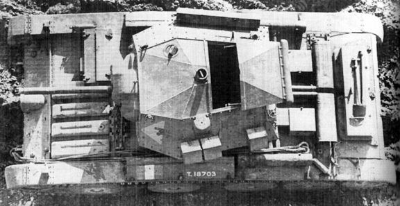
An overhead view of a Covenanter I, in British service, bearing British War Department number T18703, which was built under Contract number T.7219, by English Electric Valve Co., showing the driver’s hatch in the closed position, and the turret full-width top hatch, in the open position. The three small external stowage bins, on the left-side of the turret, each held two 100 round drums of .303-inch ammunition, for the anti-aircraft/ground defence, .303-inch Bren light machine gun. The long bin on the right-side of the turret, was for the stowage of the .303-inch Bren light machine gun, when not in use. The marking on the front left-side of the turret, is that of the British Royal Armoured Corps Gunnery School, which was located at Lulworth Camp, Dorset. Source: authors’ collection.
Near the end of April 1942, all four of these Covenanter I tanks, were withdrawn from service with Headquarters, 1st Canadian Army Tank Brigade, and sent to No. 1 Canadian Base Ordnance Depot, Royal Canadian Ordnance Corps, located at Bordon Camp, Hampshire, where they were inspected for any mechanical faults, and insuring that all the appropriate tank tools and equipment for each individual tank were in place, and if not, noting what deficiencies there were, before they were passed back to the British. Covenanter I tanks, T18366, T18368, and T18715, were returned to the British, from No. 1 Canadian Base Ordnance Depot, on 10 June 1942, with T7127, following on 16 June. Of interest, T7127, and T18366, went to the British Guards Armoured Training Regiment, while T18368, and T18715, went to the 54th Training Regiment, Royal Armoured Corps.
To replace these four Covenanter I tanks, Headquarters, 1st Canadian Army Tank Brigade, were issued with four of the newly built, Covenanter IV tanks, which were built to Covenanter III production standards (built-in engine cooling modifications), but with additional built-in cooling system modifications. On 29 April 1942, two Covenanter IV tanks, bearing British War Department numbers T81688, and T81718, respectively, both of which were built under contract number T.2075, by the English Electric Valve Co., were issued to Headquarters, 1st Canadian Army Tank Brigade. This was followed on 30 April, by the issue of the last two Covenanter IV tanks, bearing British War Department numbers T81692, and T81738 respectively, again, both of which were built under contract number T.2075, by the English Electric Valve Co. These four Covenanter IV tanks, from the time they were issued, until withdrawn from service with Headquarters, 1st Canadian Army Tank Brigade, were all reflected as ‘ready for battle,’ on the ‘State of Readiness Return,’ for the months of May 1942, through to March 1943, except for February 1943, when one was in workshops for minor repairs.
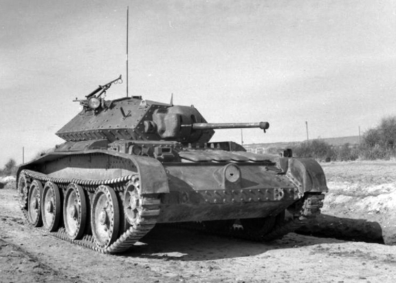
An unidentified standard production Cruiser Tank Mark V Covenanter, photographed on 11 March 1942, somewhere in the United Kingdom. Source: IWM (H 17807)
On 19 March 1943, the Canadian Army Overseas, decided to immediately re-equip the 1st Canadian Army Tank Brigade, with the Canadian designed and built, Cruiser Tank, Ram, Mark II10. This decision was followed shortly afterwards, by that of re-equipping all Canadian Armoured Corps formations overseas with the American designed, Medium Tank, M4 series, Sherman, instead of with the Canadian Ram tank. Through the spring of 1943, the four Covenanter IV tanks, of Headquarters, 1st Canadian Army Tank Brigade, were withdrawn from service, and returned to the British, and were replaced with four Sherman V11 tanks.
Although the Covenanter I, was deemed unfit for foreign service, and the Covenanter IV, was deemed fit for foreign service, only ‘in an emergency,’ because of the ongoing cooling system problems with the A13 Mark III series, both types, fulfilled their roles, of equipping the ‘Fighting Group’ of Headquarters, 1st Canadian Army Tank Brigade, with the four cruiser tanks, to which they were entitled to, so as to enable the brigade headquarters, to carry out and take part in, the mobile tank training of 1st Canadian Army Tank Brigade, as a whole.
This however, is not the end of the story of the Covenanter in Canadian service, the Covenanter Bridgelayer also served within Canadian armoured formations, but that is another story, for another day.
Acknowledgements
The author wishes to thank Miss Courtney Carrier, for proofing reading and offering constructive criticism, and comments, on my draft copy of this article, and Peter Brown, for his assistance with relevant material, and his constructive criticism, and comments, on the draft, and Clive M. Law, for providing photos from the MilArt photo archives, and relevant material, and for publishing this article, and lastly, my wife, Denise, for her never-ending support and understanding.
Any errors or omissions, is entirely the fault of the author, who unfortunately, cannot always remember everything.
_____________________________________________________
Notes
1. The 2-pounder (40-millimetre) Ordnance Quick Firing gun, was the heaviest gun fitted to British tanks from 1939 to 1942, when it was superseded by the 6-pounder (57-millimetre) Ordnance Quick Firing gun.
2. The Cruiser Tank Mk III (A13 series) was the first in a long series of British cruiser tanks to feature the Christie suspension system, which had been developed by the American inventor J. Walter Christie. It allowed for independent suspension of each road wheel, which allowed considerably longer movement than conventional leaf spring systems then in common use, which allowed tanks to have considerably greater cross-country speed.
3. Both the A13 Mark I, and A13 Mark II, stood at a height of eight-feet, 6-inches.
4. 19-feet, 6-inches if the auxiliary fuel tank was fitted.
5. Each box contained one belt of 225 rounds of 7.92-millimetre ammunition, for a total of 4,050 rounds of 7.92-millimetre ammunition.
6. Carried in six drums of 100 rounds each. On some tanks, these were carried in three stowage bins on the upper left side exterior of the turret, with each bin holding two 100 round drums of .303-inch ammunition.
7. The two side fuel tanks had a capacity of 28 gallons (127 litres) each, the bottom fuel tank had a capacity of 36 gallons (164 litres), and the auxiliary fuel tank had a capacity of 33 gallons (150 litres), for a total fuel capacity of 125 gallons (568 litres).
8. In the end, the Cruiser Tank, Mark V, Covenanter (A13 Mark III), was declared obsolete, and British Army Council Instruction ACI 295/44 dated 26th February 1944, ordered that Tanks, Covenanter I, II, III, and IV, be “broken down and disposed of to salvage as soon as possible.”
9. In order to provide a positive means of identifying individual vehicles, every British military vehicle was given a separate serial number with a prefix letter denoting the type of vehicle, which for tanks, was the letter ‘T’. These numbers were officially known as War Department numbers, but were commonly referred to as Census numbers, in Canadian service, and were normally stencilled onto the vehicle in white letters 3 ½-inches high.
10. The Canadian designed and built, Cruiser Tank, Ram, Mark II, was armed with a 6-pounder (57-millimetre) Ordnance Quick Firing gun, and three .30 Calibre (7.62-millimetre) Browning machine guns, one of which was mounted co-axially in the turret with the 6-pounder, while another, was mounted in an auxiliary turret, located on the left front of the tank, or in later production vehicles, without an auxiliary turret, in a ball mount in the left front hull. The third .30 Calibre Browning machine gun, was mounted beside the commander’s hatch, on the turret roof, and used for anti-aircraft/ground defence.
11. The Sherman V, was the designation used for the American standard production Medium Tank, M4A4, Sherman tank, in British and Commonwealth service. It was armed with a 75-millimetre gun, and two, or three .30 Calibre (7.62-millimetre) Browning machine guns (one co-axially in the turret with the 75-millimetre gun, and one in a ball mount in the right front hull). In some cases, the third .30 Calibre Browning machine gun, which was used for anti-aircraft/ground defence, was replaced by a .50 Calibre (12.7-millimetre) Browning heavy machine gun.
You can rate this article by clicking o the stars below
by James J Boulton
The Province of Alberta’s Volunteer Veterans’ Reserve was established in June 1940 as an auxiliary constabulary for the observation of vulnerable points such as dams and bridges. As with other veterans’ volunteer groups, surveillance for subversive activity sadly often included attention to productive European immigrants. No arrangements were made for a uniform, but the men were provided with a black armband marked “VVR” in red and a field service cap for identification.
The basic VVR armband, manufactured by the Northwestern Manufacturing Co., and featuring a simple black cotton band with silk-screened lettering. The armband is joined by two elastic bands at the rear. Courtesy Marway Militaria
Another example of a VVR armband. The rank structure remains unknown. Courtesy Allan and Sharon Kerr, HF-01-952_det
One of the principal functions of these identifying items was to indicate to the population at large that a group such as the Reserve existed and they were issued to each full member when he had sworn his Constables Oath before a justice of the peace (1).
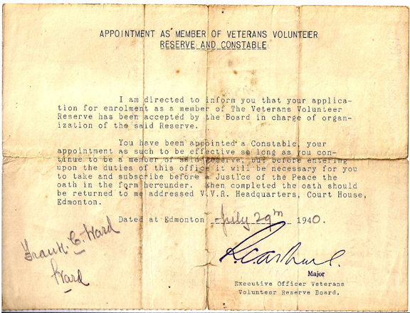
Letter of appointment to a volunteer.
The caps were fairly well constructed but in a very economical fashion. The fabric was light grey throughout. The single-layer curtain did not overlap at the front and was free along its top. There was no lining and a wide range of coloured imitation leather sweatbands were used. The unit designation “V.V.R.” was stenciled in red in the usual location for a badge and the brass 20-line civil “Canada” buttons were sewn without buttonholes.

The VVR cap emulated the army’s field service cap in design but was manufactured with the most economical material. These armband variants display VVR ranks but no documentation has been located to identify the various rank grades.
Armbands and caps were manufactured by Northwestern Manufacturing Co. Ltd. and were first issued to the larger urban units, and later to rural units (2). The armbands were black, stenciled with the letters “VVR” in red.
One of the few photos showing a group of VVR volunteers. Courtesy J.J. Boulton
What was considered to be appropriate use for the caps and armbands varied from place to place and appears to have been determined on an ad hoc basis according to common sense, military tradition and individual directives from V.V.R. Headquarters, In larger urban units, wear tended to be more strictly defined (3).
____________________________________
(1) Tingley, K. W. The Veterans Volunteer Reserve: An Auxiliary Constabulary on the Alberta Home Front, 1940-1945. Unpublished manuscript)
(2) Ibid
(3) Ibid
You can rate this article by clicking on the stars below
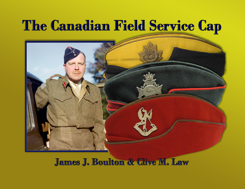
Field Service caps of the VVR, as well as other volunteers and veterans groups are covered in “The Canadian Field Service Cap” to be published in September, 2014, by Service Publications
by Clive M. Law
The outbreak of the Second World War saw a rush of men volunteer for the Canadian Active Service Force (CASF). Procurement of the necessary uniform items, including the newly adopted battle dress field service cap and Pattern 1937 Web Equipment could not keep pace with the influx of recruits. Shortages plagued the efforts of units to clothe and initiate the new recruits into the routine of army life.
Plain armband of The Royal Canadian Regiment. Black silk-screened on tan cotton. Courtesy B. Alexander © 2014. Image may not be used without express permission.

Canadian Fusiliers. Black silk-screened on natural cotton. This is one of the few that includes an image in addition to lettering. Courtesy B. Alexander © 2014. Image may not be used without express permission.
Responsibility for the recruitment and basic training of new soldiers rested on the individual regiments.[i] These regiments and corp units were challenged to outfit these volunteers and needed to identify recruits who had attested for service. To answer this many regiments adopted “CASF” armbands. These armbands identified the individual as a soldier to the civilian population while, at the same time, started the process of instilling regimental pride and identity in the soldier. The armbands filled another purpose; with the new battledress uniform, insignia was kept to a minimum and armbands were often the only distinction that identified the particular unit. Finally, they were also worn by the regimental cadre as a form of regimental identification in public.

Stormont, Dundas and Glengarry armband. This example displays their 3rd Division status. Courtesy B. Alexander © 2014. Image may not be used without express permission.

2nd Bn, Ontario Regiment. Courtesy B. Alexander © 2014. Image may not be used without express permission.
The armband was issued for a number of reasons: when battle dress was not available; where battle dress had been issued and then withdrawn for re-issue to another regiment (a news photograph shows such a case where a sergeant of the Queen’s Own Rifles wears the armband with the addition of sergeant’s chevrons); or, where the soldier was recruited into the second battalion (which had not been raised as part of the CASF) and neither the prewar Service Dress nor battle dress uniforms were available.

The Queen’s Own Rifles shown here include a sergeant (second from left) wearing a variation with smaller lettering and sergeant’s chevrons. These were worn from January to June 1940, when uniforms were withdrawn for re-issue to units which had ‘gone active’. Courtesy QOR museum
QOR armband manufactured of quality rifle green Melton wool. The scarlet lines are sewn while the regimental abbreviation is silk-screened. Courtesy QOR museum
The Canadian Army of the day was highly sensitive to the distinctions between the ‘Active’ army and the Non-Permanent Active Militia (NPAM), or reserve army, to which most second battalions belonged. This distinction was often demonstrated on the armband.
Economical construction consisting of flocked printing on a felt armband. Courtesy B. Alexander © 2014. Image may not be used without express permission.
The Royal Regiment of Canada, flocked printing on felt. Courtesy Ethan Childs
Armband to the 4th Casualty Clearing Station, Royal Canadian Army Medical Corps (Non-Permanent Active Militia). Courtesy B. Alexander © 2014. Image may not be used without express permission.
By 1940-41 stocks of uniform items were available in sufficient quantity that the armband was no longer necessary – or was worn for a very limited time during the soldier’s first few days in service, although the same situation arose when the Canadian Women’s Army Corps (CWAC) was formed in 1942. A CWAC corps armband was worn until sufficient supplies of CWAC uniform were available.

Ladies of the Canadian Women’s Army Cops are waiting for an issue of the newly designed uniform. Although no documentation has been located, the use of a common style, and the quantity required, lead the author to believe that this was an official army initiative. MilArt photo archives

CWAC armband consisting of die-cut lettering sewn to a quality Melton wool armband with khaki lining. Courtesy the late Doug Townend
No documentation on the authorities to manufacture, issue or wear these armbands has been uncovered. It is relatively certain that, with the possible exception of the CWAC armband, there was no National Defence Headquarters initiative behind their use. Design and construction vary and range from very plain (The RCR limited itself to the simple regimental abbreviation, in black, silk-screened on a khaki armband) to the thread-embroidered ‘Black Watch’ on a tartan armband. Equally varied are the materials, with a light-weight cotton being the most common but also several made of melton wool and some examples on silk.
______________________________________
[i] It would be 1942 before training was consolidated in Training Centres in order to reduce the manpower required to provide instruction and, at the same time, produce soldiers to a common standard.
You can rate this article by clicking on the stars below
by Clive M. Law
The provision of equipment with which to outfit a complete division of soldiers for the Canadian Expeditionary Force (CEF) proved to be a challenge for its small cadre of professional soldiers. The pre-war Militia attempted to mirror the British Army in many respects but was unable to invest the money required. At the same time, the Canadian Militia attempted to set a distinct Canadian style which resulted in significant differences between the soldiers of Britain and those of Canada. Best known amongst these were: the adoption of the Ross rifle in lieu of the British Enfield SMLE, the use of a different pattern khaki service dress uniform, and leather Oliver Pattern load-bearing equipment.
With mobilization came the need for a variety of other equipments which had previously been neglected by Ottawa, including a suitable entrenching tool. The Minister of Militia, Colonel Sam Hughes, addressed this item by supporting the adoption of a combination shovel and shield – a suggestion initially made by Ena MacAdam, his personal secretary, who had witnessed Swiss soldiers constructing front line fortifications in France with a similar tool.[1]
Top, The MacAdam shovel with the short handle pivoted for carry. The spike was meant to support the shield but this proved impractical and the hole was found to be too low to permit accurate sighting.
Bottom, With the handle in battery for digging.
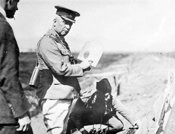
Sir Samuel Hughes holding a MacAdam Shield Shovel. PA-202396
On 3 September, 1914, Hughes submitted a recommendation for the purchase of 25,000 shovels from the Midvale Steel Company, of Philadelphia. The specifications show the shovel to be 8 1/2 inches wide and 9 3/4 inches long with a 1 1/2 inch curvature. Each blade was to feature a 3 1/4 x 2 inch hole on the left side (of the concave). The contract called for an integral handle, 4 inches long and tapering from 2 inches to 5/8 inch. The price quoted by Midvale was $1.35 per shovel and delivery was promised within 3 weeks.[2] The submission identified that the shovels were to be 3/16 inch thick and capable of ‘resisting’ three shots from a US Springfield and Ross Mk III ammunition. Midvale was to test one of every 100 shovels. In total, the MacAdam shield- shovel weighed 5 pounds 4 ounces.[3]
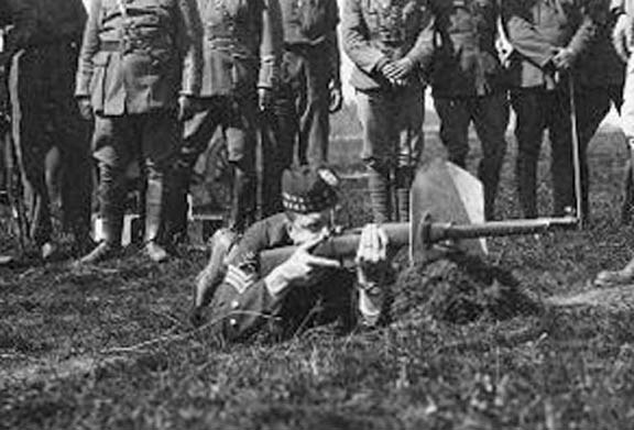
Demonstrating the MacAdam to the Minister of Defence and Staff officers at Connaught Range, Ottawa.
The First Canadian Division embarked for England with the shovel hanging awkwardly from the side of their Oliver pattern equipment. When this was later replaced with Pattern 1915 equipment there was still no specific carrier for the shovel. Incredibly, the soldier was expected to use this tool with only a 4-inch handle.That something was about to happen was hinted at when, on 9 February, 1915, Colonel John Carson, the Minister’s London-based “Special Representative” wrote:
Alderson states our shovels tried as shields but not found satisfactory. Trenching tools issued our troops. Could not carry our shovels in addition so they were left behind.
Lt-General E.A.H. Alderson, was the General Officer Commanding the 1st Canadian Division. A professional soldier he was selected as he had previously commanded Canadians in South Africa, however, there was little love lost between Carson and Alderson.
The idea that the MacAdam shovels were left behind in Great Britain when the CEF sailed for France infuriated Hughes who immediately wrote back:
No authority given anyone purchase other shovels [this] order must be cancelled and Canadian shovels used[.] you must hold a tight hand on all that improper work over there[.] promptly cancel order for English entrenching tools[.] see General Alderson and if necessary Earl Kitchener but I will not permit this improper interference[.] British entrenching tool absolutely useless for any purpose[.] ours perfect for protection and with handle attached is excellent for shovelling (sic)[.] collect every Canadian shovel and have handles attached thereto[.] man sent over with handles to do the work please act promptly.
Finally, in mid-February, 1916, the War Office sent a telegram to the Department of Militia and Defence identifying a number of discrepancies in the stores of the 1st Canadian Division which were resolved prior to its embarkation for France. In addition to horse harness, boots and wagons was resolution over the shovel;
Only five battalions were in possession of Web equipment, remaining battalions having Oliver equipment, which had no pack or facilities for carrying the entrenching implement and were therefore completed with Web before embarkation.
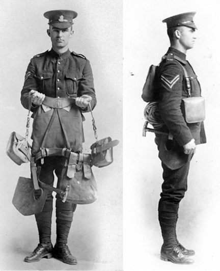
Oliver Pattern equipment with the MacAdam shovel strapped on as an after-thought. MilArt photo archives
Hughes was not one to accept this decision at face value and continued to argue in favour of ‘his’ shovel. In fact, in March of 1915 (3 weeks after being advised that the CEF had sailed for France with British entrenching tools and that the Canadian shovels had been left behind) approval was sought, and obtained, to order the manufacture of 25,000 handles from the Nova Scotia Steel Company, at a total cost of $3,800. Unfortunately, the records are silent on whether these were manufactured and, if so, delivered to the UK.
In 1917 the British War Office sought approval from Canada to dispose of the shovels as they represented 50 tons of steel, a valuable wartime commodity, and in early April Canada agreed to dispose of these to the War Office. The surviving 22,000 shovels which had cost the government over $29,000 was sold off as scrap in 1917 for $1,400. Few of these shovels have survived although it is believed that an example exists in the collection of the Imperial War Museum as well as with the Royal Winnipeg Rifles museum.
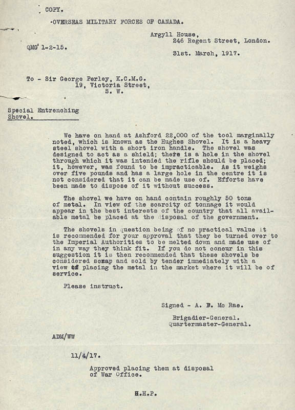
Correspondence on the ultimate disposal of the shovels. Library and Archives Canada e000000301
Notes;
1. Ronald G. Haycock, Sam Hughes: The Public Career of a Controversial Canadian, 1885-1916 (Toronto: Wilfrid Laurier University Press, 1986).
2. Privy Council, Order-in-Council 2302 of 4 September 1914
3. Rawling, William, Surviving Trench Warfare.
You can rate this article by clicking on the stars below
Bill Alexander ©2014
During the Second World War, the 31st (Alta.) Recce. Regt. embarked on what can only be described as an odyssey in their efforts to acquire an officially approved embroidered title. The new unit was organized on March 18, 1942 and drew heavily on volunteers from the 15th Alberta Light Horse and the 19th Alberta Dragoons. Discussions between the two reserve regiments and the Officer Commanding the 31st resulted in a request that the 31st be granted permission to wear the 15th Alberta Horse cap badge, while the 19th Dragoons cap badge would be worn in the manner of cavalry units, on the chevrons or sleeves of the senior NCOs. By established policy, the shoulder title would be based on the authorized unit designation. It appears the rationale behind unit designations and insignia had not been clearly communicated at all senior levels. In February, 1943, Maj.-Gen. J.V. Young , Master General of the Ordnance (MGO), noted that the unit designation did not reflect the parent regiments, and suggested that the designation be changed to the 31st (15th/19th Alberta) Reconnaissance Regiment. This would connect the cap badges to the unit, and this designation would be the basis for shoulder insignia.[1]
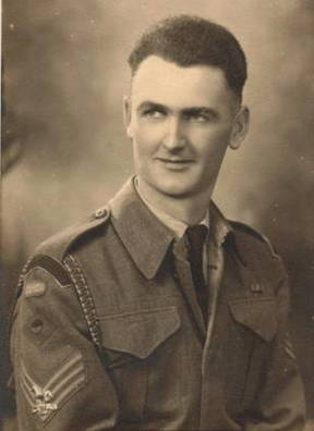
A sergeant of the 31st (ALTA) RECCE REGT wearing the first pattern shoulder title, the Pacific Command formation sign, with imposed blue over red circle, and the 19th Alberta Dragoons cap badge on his sergeant’s chevrons. Author’s collection. May not be used without permission.
The suggested designation was met with less than enthusiasm. The Officer Commanding (CO), 31st Recce indicated: “It is felt that the suggested name “31st (15th/19th Alberta) Reconnaissance Regiment” is too lengthy and cumbersome, and it is desired the present name be retained.” [2] Both the designations and the desire to associate the unit to the reserve regiments caused consternation in the offices of Director Ordnance Services (Administrative). DOS (A) was concerned that there was no obvious connection between the existing unit designation and the regimental cap and sleeve badges the 31st would wear. And, there was still a possibility one or both of the reserve units could be mobilized, duplicating demand for regimental badges. Lt.-Col. Tosland, Officer Administering the Canadian Armoured Corps, added his opinion, nominating the use of “31st Recce (15/19 ALTA.) REGT.”, noting his designation was not any longer than “20th Army Tank Regt (16/22nd SASK. HORSE)”. After this recommendation, the MGO stepped back into the discussion, and suggested the unit designation be 31st (15/19 Alta) Recce. Regt. C.A.C. In his opinion this was not unduly long, and it was similar to the designation recently adopted by the 18th Manitoba Armoured Car Regiment. A further variation was suggested, which added “H” and “D”, for Hussars and Dragoons, after the regimental numbers. The OC of the 31st Recce did not respond to any of these proposed designations.[3]
The question of the proper unit designation continued to elicit responses from various sources. The Director of Administration, after some research, suggested the designation “31st Reconnaissance Regiment 15/19 Alberta (Dragoons)”. After some discussion about the use of brackets, the new designation made its way through official channels. The Adjutant General’s office waded in with their opinion, suggesting the CO 31st Recce accept the revised designation proposed by the D of Admin. Lt.-Col. Hudson, from DOS (A), noted “as the question of provision of badges is entirely contingent upon the title of the Regiment, it is recommended that action be taken to have the title finally decided upon and authorized first.”[4] His advice had little effect. The CO of the 31st was away on course, and no decision could be made on the revised designation until his return. In the middle of June a cable to NDHQ indicated the CO would not accept DRAGOONS in the designation, and it was suggested that “Alta” be removed. Over six months had passed, and still the question of the designation remained unresolved.
Frustration was growing in army administrative circles. Lt.-Col. Tosland, now in the office of the Director of Organization noted the matter had been “dragging along for some considerable time”, and in a June memo suggested yet another designation, 31st RECCE REGT. (15/19 ALTA) C.A.C. The D. of Admin, in a very frank response, noted:
1. Like you I am getting very bored with this argument. It appears that the C.O. of the 31st Recce. Regt. knows very little about army history. A Recce Regt is obviously of a cavalry nature and to put 15/19 without any qualifications seems stupid.
2. The war must go on and we have not got time to teach people very much. Therefore any decision you make will not be objected to by this Directorate.
3.In any event, I imagine the unit will be disbanded in the post-war reorganization and probably become known as the Alberta Tommy Gun Fusiliers. [5]
In the interim, the 31st had taken the matter into their own hands, and purchased shoulder titles using regimental funds. Employing the original designation, “31st (ALTA.) RECCE. REGT.”, the titles were embroidered in red lettering on a navy field, sewn on a second layer of gray melton material, creating a gray margin. These were acquired and issued to the personnel of the regiment without official authorization.

The first pattern shoulder title, regimentally procured. Note the two piece construction and flat topped “3”. Author’s collection, not to be used without permission.
On June 21, Lt.-Col. Tosland finally submitted an official re-designation for the unit reading, “31st Recce. Regt. (15/19 Alta) C.A.C.”. The next day, a memorandum from DOS (A) requested that the regimentally procured embroidered title be approved and contracts let. An example had already been submitted as a pattern to DOS (A). In a marginal note on the same memo, Tosland indicated:
It is considered preferable that the shoulder titles conform with the unit title (sic) and it is suggested that GOC in C Pacific Command be asked to submit alternative designs based on the proposed title of 31st Recce Regt (15/19 Alta) CAC. [6]
The proposed change continued to cause ire in official circles. A memo addressed to the Deputy Adjutant General from DOS (A) argued the proposed designation was meaningless, and requested the designation remain unchanged. The regiment also protested, arguing an embroidered title was already in use, and an inventory existed which had been acquired at regimental expense. If NDHQ required a change, compensation would be required for these outlays. Common sense finally prevailed, and the original designation, 31st (ALTA.) RECCE. REGT. was deemed the official designation. The request to keep the existing design was accepted and the embroidered title submitted by the regiment was approved. [7]
With the designation question finally settled, the 31st (Alta.) Recce argued that their titles acquired at regimental expense should be considered a government issue, and therefore the unit should be reimbursed for their cost. For 2,128 titles, the unit had paid $1,038.40. NDHQ balked at the submission. In a letter, the MGO noted:
It is considered that the price paid (Approximately 48 cents per pair) is excessive and, as these badges were purchased prior to NDHQ approval being obtained, authority cannot be granted.[8]
A General Allowance Claim for $320.00 was granted, which compensated the unit at a rate of 15¢per pair. It was noted that the reimbursement was in line with regular contract prices for titles. It was the middle of November before the cheque was cut.
The second pattern title made by Stanley A.Grant Toronto. One piece construction with an embroidered white border. Note the rounded “3”. Author’s collection, not to be used without permission.
Despite the approval, action to obtain sealed samples had not been initiated. Having a supply of insignia on hand had precluded immediate procurement action. But the inventory was quickly run down, and it was discovered that after the July approval, no further steps had been taken to acquire insignia. In December, an urgent request for six samples of the 31st title was sent to the Inspection Board. The manufacturer, Stanley A. Grant of Toronto, returned six samples, but they differed significantly from the pattern submitted by the regiment. The Grant samples were made on one layer of material, reading “31st (ALTA.) RECCE. REGT.”, in red on a dark blue field with a white embroidered border. The spectre of another prolonged debate about proper insignia loomed, and the decision was referred to the CO of the 31st. With a degree of relief, these titles were finally accepted by Lt.-Col. H.H. Riley, CO of the 31st, on January 19, 1944. An indent was let for a production run, and the second pattern of title was taken into wear. The Grant pattern title continued in wear until the 31st (ALTA.) RECCE. REGT. was disbanded in the United Kingdom on February 15, 1945. There, the personnel of the unit were allocated to the reinforcement depots. [9]
The saga of the 31st Recce Regiment shoulder title was atypical of procurements. Most shoulder title authorizations moved through the system in a timely fashion. The attempt to please all parties with an acceptable designation had only led to confusion, frustration and long delays. As predicted, the regiment was not perpetuated in the post war army re-organization, and the 31st (ALTA.) RECCE. REGT. disappeared into the annals of history. Their shoulder titles remain as the only artefact to mark their contribution to Canada’s war effort: no Alberta Tommy Gun Fusiliers were raised to perpetuate the unit.
[1] Potts A.E. Maj.Gen. GOC 6th Canadian Division, Letter, Regimental Dress, 31 (Alta) Recce Regt C.A.C., December 5, 1942. Young J.V. Maj.-Gen. MGO Reply to GOC 6th Canadian Division, January 8, 1943. LAC RG 24 Vol. 2266, File HQ 54-28-1299-2. The use of the 15th ALH cap badge was based on seniority of the two units involved. Within months the use of the 19th Alberta Dragoons badges was forgotten. The 15th ALH and the 19th Alberta Dragoons only had slip-on titles authorized during the war. The 19th Alberta Dragoons coloured embroidered title was not authorized until post war.
[2] Presont J.F. Brig. Fortress Commander, Esquimalt Fortress, Letter Regimental Insignia Dress Regulations 31st (Alta) Recce Regt C.A.C., CA. March 12, 1943. The 31st was under command of the Fortress Commander at this time.
[3] Tosland A.L. Lt.-Col. OA CAC, Memorandum, Dress 31st (Alta.)Recce Regt. C.A.C., to DOS (A), March 27, 1943. LAC RG 24 Vol 2266. Unidentified Lt.-Col., for the MGO, Letter, Regimental Dress, 31st (Alta) Recce. Regt. C.A.C., March 30, 1943. The variations for the designation were all upper case. The post numeric D and H were to represent Dragoons and Hussars. It is unclear where the Hussar affiliation came from.
[4] It was argued that Dragoons should be an acceptable designation, as the D of Admin believed the 15th ALH had at one time a Dragoon regiment in their lineage.
[5] Unidentified Colonel, D. of Admin, Memorandum Regimental Dress, 31st (Alta) Recce. Regt., to D. Org., June 18,1943. LAC RG 24 Vol 2266.
[6] Saunders R.P. Col. DOS (A), Memorandum to Dir. of Org., June 22, 1943. LAC RG 24 Vol 2266.
[7] Tosland A.L. Lt.-Col. for Adjutant General, Telegraph to GOC in C Pacific Command. July 10, 1943. LAC RG 24, Vol. 2266. It was also agreed that the cap badge of 15 Alberta Light Horse would be worn by the 31st. The 19th Dragoon badge was worn unofficially as a sleeve badge
[8] Young J.V. Maj.-Gen. MGO, Letter to GOC in C Pacific Command, September 25, 1943. LAC RG 24 Vol. 2266.
[9] Various memoranda and letters, 31st (Alta) Recce Regt. LAC RG 24 Vol. 2266. The Inspection Board of the United Kingdom and Canada was a wartime agency that monitored the contracts and quality of goods and materials ordered by the governments of the two nations.
You can rate this article by clicking on the stars below.
by Mark W. Tonner
As noted in the last paragraph of Part 2, the Calgary Regiment as of 31 October 1941, held 47 Mark IIA* Matilda III and two Mk IIA* Matilda III Close Support tanks. According to their war diary for October 1941, these tanks were distributed throughout the regiment as follows:
- Headquarters Squadron with four Matilda Mark IIA* Matilda III tanks
- “A” Squadron with 14 Mark IIA* Matilda III tanks and one Mark IIA* Matilda III Close Support tank
- “B” Squadron with 15 Mark IIA* Matilda III tanks
- “C” Squadron with 14 Mark IIA* Matilda III tanks and one Mark IIA* Matilda III Close Support tank
Likewise, the 42 Mark IIA* Matilda III tanks held by the Three Rivers Regiment, at this time, were similarly distributed throughout the regiment.

T29826, a Mark IIA* Matilda III Close Support tank, named ALBERTA, of “A” Squadron Headquarters, the Calgary Regiment, which was taken-on-charge of the Canadian Army Overseas on 24 September 1941. Source: authors’ collection.
Beginning in November 1941, as more of the new Infantry Tank Mark IV, Churchill (A22), became available for issue to 1st Canadian Army Tank Brigade, the Mark IIA* Matilda III tanks started to be withdrawn from service with the Three Rivers Regiment, and the Calgary Regiment. By 30 November, 12 Matilda tanks, had been withdrawn from the Three Rivers Regiment, leaving them with a total of 30 Mark IIA* Matilda III tanks remaining on their strength, while by the same date, the Calgary Regiment’s war diary reflects that they held 27 Mark IIA* Matilda III and two Mark IIA* Matilda III Close Support tanks. Thus, by 30 November, 1st Canadian Army Tank Brigade held a total of 57 Mark IIA* Matilda III and two Mark IIA* Matilda III Close Support tanks. During the month of December 1941, a total of 37 Mark IIA* Matilda III tanks, were struck-off-strength of the Canadian Army Overseas and returned to the British, through No. 1 Canadian Base Ordnance Depot. The Three Rivers Regiment, had returned their last Matilda tank to No. 1 Canadian Base Ordnance Depot, on 24 December 1941, while the Calgary Regiment had stopped using their Matilda tanks on 2 December, concentrating instead, on tank crew training with their newly issued Infantry Tank Mark IV, Churchill (A22) tanks. As of 31 December, the Three Rivers Regiment, and the Calgary Regiment, no longer held any Matilda tanks on their charge, having returned them all to No. 1 Canadian Base Ordnance Depot, in exchange for the new Infantry Tank Mark IV, Churchill (A22). Also, as of 31 December 1941, No. 1 Canadian Base Ordnance Depot held a total of 53 Mark IIA* Matilda III and two Mark IIA* Matilda III Close Support tanks, on Canadian charge.
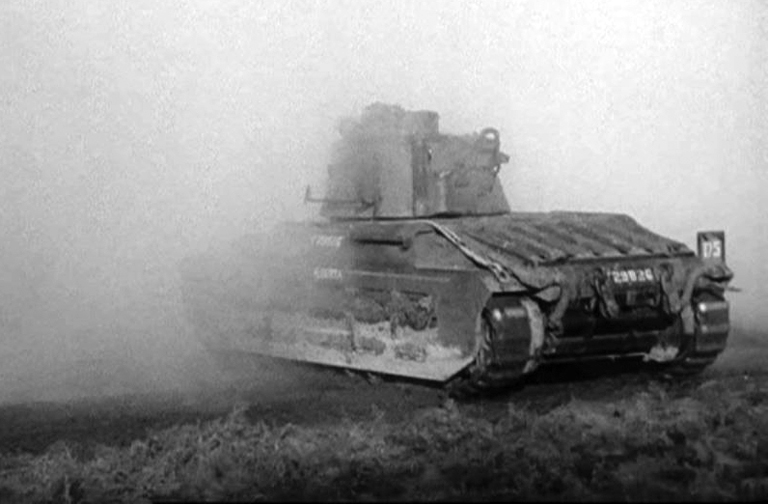
A rear view of T29826, a Mark IIA* Matilda III Close Support tank, of “A” Squadron Headquarters, the Calgary Regiment. The number ‘175,’ that appears on the plate mounted on the right-rear track guard, is the Arm of Service marking, by which the Calgary Regiment’s vehicles were identified throughout the period of the Second World War. For the Calgary Regiment, the Arm of Service marking, was a horizontally divided blue over brown coloured square, with the superimposed, centrally located three digit number ‘175,’ in white. Source: authors’ collection.
Throughout January 1942, a further 37 Mark IIA* Matilda III and two Mark IIA* Matilda III Close Support tanks, were struck-off-strength of the Canadian Army in the United Kingdom, and returned to the British, from No. 1 Canadian Base Ordnance Depot, leaving a total of 15 Mark IIA* Matilda III tanks held on charge of the depot, as of 31 January 1942. On 22 February 1942, a Mark IIA Matilda II (equipped with twin AEC diesel engines) was taken on Canadian strength from the British by No. 1 Canadian Base Ordnance Depot, and was in turn, issued to No. 1 Canadian Ordnance Reinforcement Unit, for the training of vehicle mechanics. Also, February 1942, saw a further 11 Mark IIA* Matilda III tanks struck-off-strength and returned to the British, leaving a total of four Mark IIA* Matilda III tanks held on charge of No. 1 Canadian Base Ordnance Depot, as of 28 February, 1942.
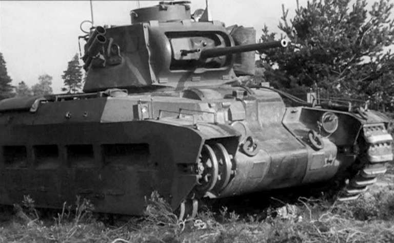
On 4 November 1941, the Calgary Regiment was detailed to send a Mark IIA* Matilda III tank, to Grayshott, Hampshire, to have various pictures taken for the British War Office. While involved in this task, this unidentified tank suffered a track breakage, to the delight of the photographers. The marking, which appears on the lower-left corner of the nose plate, is the formation marking, that was used to identify vehicles of the 1st Canadian Army Tank Brigade, at this time. This formation sign was a gold or yellow maple leaf centred on a black background square, with a black left-facing image of a ram superimposed centrally on the maple leaf. Source: authors’ collection.
These four Mark IIA* Matilda III tanks, were struck-off of Canadian charge and returned to the British, on 7 April 1942, thus leaving only the solitaire Mark IIA Matilda II tank on charge of No. 1 Canadian Ordnance Reinforcement Unit, as the only Matilda tank held on strength of the Canadian Army in the United Kingdom. As of 5 September 1942, this tank was still held by No. 1 Canadian Ordnance Reinforcement Unit, as reflected in a report entitled “A” Vehicles On Loan, that was submitted to the Director of Ordnance Services at Canadian Military Headquarters, London, from the officer commanding the Vehicle Census Branch of No. 4 Sub-Depot, No. 1 Canadian Base Ordnance Depot, Bordon Camp, Hampshire. This report listed all of the “A” vehicles that were held on the Canadian Census as being on loan from British sources. As of 1 December 1943, the Canadian Army in the United Kingdom, no longer held any type of infantry tank on strength, all (including the Mark IIA Matilda II tank held by No. 1 Canadian Ordnance Reinforcement Unit) had been struck-off of Canadian strength and returned to the British.
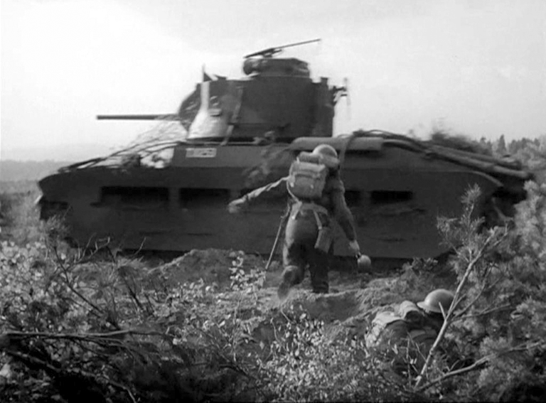
Left-hand side view of T10253, a Mark IIA* Matilda III, barring the markings of “C” Squadron Headquarters, the Calgary Regiment (the ‘F’ within a circle on the turret side, just below the turret lifting eye), during a ‘Tank Hunting’ demonstration with a platoon of the 3rd Canadian Divisional Infantry Reinforcement Unit, in the vicinity of Headley, Hampshire, on 9 October 1941. Source: authors’ collection.

Front view of T10253, a Mark IIA* Matilda III, during a ‘Tank Hunting’ demonstration with a platoon of the 3rd Canadian Divisional Infantry Reinforcement Unit, in the vicinity of Headley, Hampshire, on 9 October 1941. Source: authors’ collection.
General characteristics/specifications of the Infantry Tank Mark II, Matilda II (A12)
(Mark IIA Matilda II, Mark IIA* Matilda III, and the Mark IIA* Matilda III Close Support)
Crew:
- 4 (Commander, gunner, loader/operator, driver)
Weight (fully loaded):
- approximately 25-tons
Length:
- without auxiliary fuel tank fitted: 18-feet 9-inches
- with auxiliary fuel tank fitted: 19-feet 9-inches
Width:
- 8-feet 3-inches
Height:
- 8-feet 5-inches
Ground clearance:
- 13-inches
Ground pressure:
- 20-pounds per square inch
Maximum speed:
- 15-miles per hour
Maximum cross country speed:
- 8-miles per hour
Fording depth:
- flaps open: 3-feet
- flaps closed: 3-feet 6-inches
Vertical obstacle:
- 2-feet
Trench crossing:
- 7-feet
Track length:
- 6-feet 9½-inches (69 shoes per track)
Track width:
- 14-inches
Main Armament:
- 2-pounder Ordnance Quick Firing gun Mark IX or Mark X (Mark IIA Matilda II, and Mark IIA* Matilda III), or a 3-inch Howitzer Ordnance
Quick Firing Mark I or Mark IA (Mark IIA* Matilda III Close Support)
Secondary Armament:
- 7.92-millimetre Besa machine gun (Mark IIA Matilda II, and Mark IIA* Matilda III, and Mark IIA* Matilda III Close Support)
- twin 4-inch electrically fired smoke generator (No. 2 Mark I) discharger mounted on right forward turret side (Mark IIA Matilda II, and Mark IIA* Matilda III, and Mark IIA* Matilda III Close Support)
- Bren .303-inch light machine gun for anti-air craft/ground defence (Mark IIA Matilda II, and Mark IIA* Matilda III, and Mark IIA* Matilda III Close Support)
Elevation:
- 2-pounder Ordnance Quick Firing gun Mark IX or Mark X – minus 15 degrees to plus 20 degrees
- 3-inch Howitzer Ordnance Quick Firing Mark I or Mark IA – minus 20 degrees to plus 20 degrees
Muzzle velocity:
- 2-pounder Ordnance Quick Firing gun Mark IX or Mark X – 2800-feet per second
- 3-inch Howitzer Ordnance Quick Firing Mark I or Mark IA – 600 to 700-feet per second
Armour thickness:
- maximum: 3-inches
- minimum: 1-inch
Engine:
- Twin Leyland 6-cylinder diesels, 95-horsepower each (Mark IIA* Matilda III, and Mark IIA* Matilda III Close Support)
- Twin AEC 6-cylinder diesels, 87-horsepower each (Mark IIA Matilda II)
Fuel tanks:
- two tanks of 23.25 gallons each, with a total fuel capacity of 46.5 gallons
Auxiliary fuel tank:
- with a total fuel capacity of 36 gallons
Maximum cruising range:
- 160-miles
Turret rotation:
- hydraulic power or by hand, 360-degree traverse (complete rotation in 14 seconds using hydraulic power)
Vision arrangements:
- three Vicker’s Tank Periscope Mk IV, and observations slits (Commander, gunner and driver)
Ammunition stowage:
- 93 rounds 2-pounder (Mark IIA Matilda II, and Mark IIA* Matilda III)
- 36 rounds smoke and 18 rounds high explosive 3-inch howitzer (Mark IIA* Matilda III Close Support)
- 2925 rounds 7.92-millimetre (13 belts of 225 rounds each) (Mark IIA Matilda II, and Mark IIA* Matilda III)
- 2025 rounds 7.92-millimetre (9 belts of 225 rounds each) (Mark IIA* Matilda III Close Support)
- 8 smoke generators (Mark IIA Matilda II, and Mark IIA* Matilda III, and Mark IIA* Matilda III Close Support)
- 600 rounds .303-inch in six 100 round drums, 10 rifle grenade cartridges .303-inch for smoke generator dischargers (Mark IIA Matilda II, and Mark IIA* Matilda III, and Mark IIA* Matilda III Close Support)
Remarks:
- two Pyrene fire extinguishers, came with each Matilda, one located in the driver’s compartment, while the other was located in the fighting compartment. A 30-foot steel towing hawser, along with four lifting and towing links, and six spare track links (with 12 spare track pins), was also provided with each tank. Both Makers’ Special tools (specific tools provided by the manufacturer with each tank), and a set of Driver’s tools, along with a gearbox clutch spanner, and a grease gun, with a ball swivel nozzle, were provided, along with a 5-ton capacity jack. Other miscellaneous tools provided were, a pickaxe, a General Service shovel, a 15-inch matchet, with sheath, and a 3-foot 6-inch crowbar.

View of the twin AEC 6-cylinder diesel engines that were used in the Mark IIA Matilda II, as used by the Canadian Army Overseas. Source: authors’ collection.
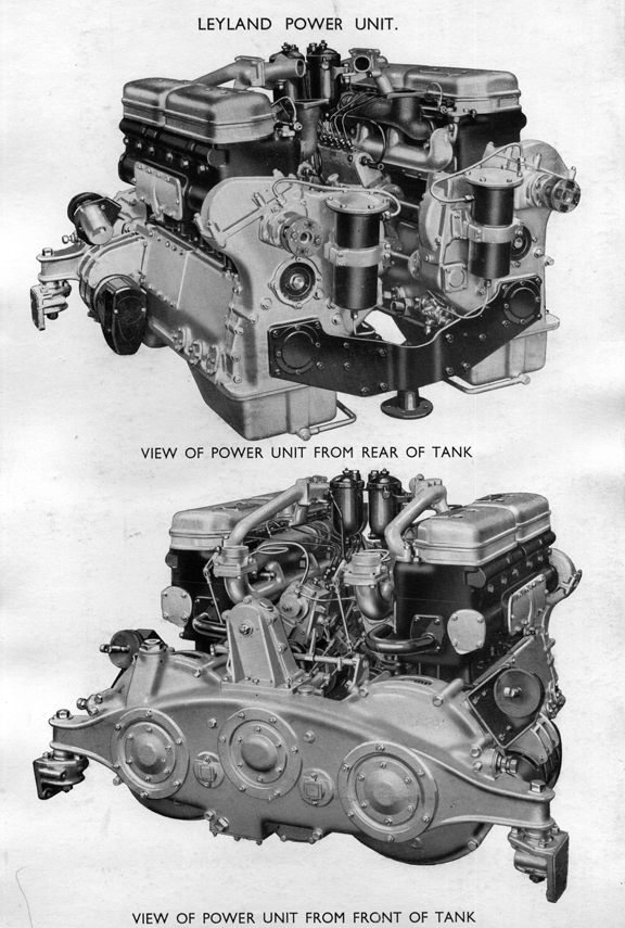
View of the twin Leyland 6-cylinder diesel engines that were used in the Mark IIA* Matilda III, and in the Mark IIA* Matilda III Close Support, as used by the Canadian Army Overseas. Source: authors’ collection.
Acknowledgements:
The author wishes to thank Miss Courtney Carrier, for proofing reading and offering constructive criticism, on my draft copies of this article, so as to keep it simple for all to read, and Peter Brown, for his insight and assistance with relevant material, and my good friend Clive M. Law, for providing photos from the MilArt photo archives, and for publishing this article, and lastly, my wife, Denise, for the extra set of eyes, while studying various photos, and for her never-ending support and understanding.
You can rate this article by clicking on the stars, below.
